User guide
User guide
English
Contents
Introduction .......................................................................................................................... 1
Indications for use ............................................................................................................ 1
Indications for use (USA only) ........................................................................................... 1
Contraindications .............................................................................................................. 1
Adverse effects ................................................................................................................ 2
General warnings and cautions ......................................................................................... 2
The Astral device ................................................................................................................. 4
The Astral device interface ............................................................................................... 5
Touch screen .................................................................................................................... 6
Information bar ................................................................................................................. 7
Menu bar .......................................................................................................................... 8
Bottom bar ....................................................................................................................... 8
Main screen ..................................................................................................................... 8
Pressure bar ..................................................................................................................... 9
Using the Astral device ...................................................................................................... 10
Using the Astral device for the first time ........................................................................ 10
Powering on the device .................................................................................................. 11
Powering off the device ................................................................................................. 11
Enhanced access feature ............................................................................................... 12
Starting and stopping ventilation .................................................................................... 14
Locking and unlocking the touch screen ......................................................................... 14
Navigating the menus..................................................................................................... 15
Monitors menu ................................................................................................................................15
Setup menu .....................................................................................................................................17
Alarms menu ...................................................................................................................................17
Information menu ............................................................................................................................18
Device settings...............................................................................................................
18
Adjusting device settings ..................................................................................................................19
Programs ........................................................................................................................ 19
Manual Breath feature .................................................................................................... 20
Sigh Breath feature ........................................................................................................ 20
Travelling with the Astral device ..................................................................................... 21
Assembling patient circuits ............................................................................................... 21
Circuit options ................................................................................................................ 21
Fitting the circuit adapter ................................................................................................ 23
Connecting a single limb circuit with intentional leak ...................................................... 23
Connecting a single limb circuit for invasive use ...............................................................................24
Connecting a single limb circuit with expiratory valve ..................................................... 25
Connecting a double limb circuit (Astral 150 only) .......................................................... 27
Connecting a mouthpiece circuit .................................................................................... 28
Learn Circuit ................................................................................................................... 29
Accessories ......................................................................................................................... 32
Power accessories .......................................................................................................... 32
Optional accessories ....................................................................................................... 32
Attaching patient circuit accessories ............................................................................... 32
Attaching a humidifier ....................................................................................................................... 33
Attaching a Heat Moisture Exchange (HME) .................................................................................... 34
Attaching an antibacterial filter ......................................................................................................... 34
Adding supplemental oxygen ........................................................................................................... 35
Monitoring delivered oxygen ............................................................................................................ 37
Attaching a nebuliser ........................................................................................................................ 37
Attaching other accessories ............................................................................................ 38
Attaching a pulse oximeter ............................................................................................................... 38
Attaching a remote alarm ................................................................................................................. 40
Power management........................................................................................................ 41
Connecting to mains power ............................................................................................................. 42
Connecting the Astral External Battery ............................................................................................ 43
Connecting to a ResMed Power Station (RPSII) .............................................................................. 44
Connecting to an external DC power source .................................................................................... 44
Using the internal battery ................................................................................................................. 45
Device power source indicators ....................................................................................................... 47
Astral Carry Bag .............................................................................................................. 48
Alarms ................................................................................................................................. 49
Alarm priority .................................................................................................................. 50
Viewing the active alarms ............................................................................................... 52
Muting alarms ................................................................................................................. 52
Resetting alarms ............................................................................................................. 53
Adjusting the alarm volume ............................................................................................. 53
Testing the alarm sounders and indicators ...................................................................... 54
Testing the Remote Alarm .............................................................................................. 55
Testing the alarms .......................................................................................................... 55
Power alarms .................................................................................................................. 56
Detecting circuit disconnection and de-cannulation ........................................................ 57
Astral Disconnection Alarm ............................................................................................. 58
Adjusting the Disconnection Alarm ................................................................................. 58
Data management process ................................................................................................ 59
Cleaning and maintenance ................................................................................................ 60
Weekly ............................................................................................................................ 60
Monthly........................................................................................................................... 60
Servicing ......................................................................................................................... 61
Replacing the air filter ..................................................................................................... 61
Maintenance Timetable .................................................................................................................... 62
Internal Battery ................................................................................................................................. 62
Device information ........................................................................................................................... 63
Troubleshooting ................................................................................................................. 64
Alarm troubleshooting ..................................................................................................... 64
Learn Circuit troubleshooting .......................................................................................... 68
General troubleshooting .................................................................................................. 71
Technical specifications ..................................................................................................... 72
Guidance and Manufacturer’s Declaration Electromagnetic Emissions & Immunity ....... 77
Guidance and manufacturer’s declaration—electromagnetic emissions...........................................77
Guidance and manufacturer’s declaration – electromagnetic immunity............................................78
Recommended separation distances between portable and mobile
RF communications equipment and the life support device .............................................................80
Potential impact of electromagnetic disturbances ............................................................................80
Symbols .............................................................................................................................. 81
Standards compliance ....................................................................................................... 82
Training and support ......................................................................................................... 82
Limited warranty ................................................................................................................ 83
Appendix A: Definitions ..................................................................................................... 84
Ventilation settings definitions ........................................................................................ 84
Measured and calculated parameter definitions ............................................................. 86

Introduction
English 1
Introduction
The Astral device provides mechanical ventilation to both ventilation dependent and non-dependent
patients. It delivers pressure and volume ventilation through either a valve or leak circuit, and is
compatible with a range of accessories to support specific use cases.
The information in this guide applies to both the Astral 100 and the Astral 150 devices. Where
information applies to only one of these devices, that device will be specified.
Note: Some features may not be available on your device.
This User Guide is for a patient or carer user, and does not contain all the information provided in the
Clinical Guide.
WARNING
•
Read the entire manual before using the Astral device.
• Use the Astral device only as directed by a physician or healthcare provider.
• Use the Astral device only for the intended use as described in this manual. Advice contained
in this manual does not supersede instructions given by the prescribing physician.
• Install and configure the Astral device in accordance with the instructions provided in this
guide.
CAUTION
In the US, Federal law restricts this device to sale by or on the order of a physician.
Indications for use
The Astral 100/150 provides continuous or intermittent ventilatory support for patients weighing more
than 5 kg who require mechanical ventilation. The Astral device is intended to be used in home,
institution/hospital and portable applications for both invasive and non-invasive ventilation.
Indications for use (USA only)
The Astral 100/150 provides continuous or intermittent ventilatory support for patients weighing more
than 11 lb (5 kg) who require mechanical ventilation.
The iVAPS mode with optional AutoEPAP is intended for patients weighing more than 66 lb (30 kg).
The Astral device is intended to be used in home, institution/hospital and portable applications for both
invasive and non-invasive ventilation.
CAUTION
The Astral device is not intended for use as an emergency transport ventilator.
Contraindications
The Astral device is contraindicated in patients with the following pre-existing conditions:
• pneumothorax or pneumomediastinum
• pathologically low blood pressure, particularly if associated with intravascular volume depletion
• cerebrospinal fluid leak, recent cranial surgery or trauma
• severe bullous lung disease
• dehydration.

Introduction
2
WARNING
AutoEPAP is contraindicated when using an invasive interface.
Adverse effects
Report unusual chest pain, severe headache or increased breathlessness to your physician. The following
side effects may arise during use of the device:
• drying of the nose, mouth or throat
• nosebleed
• bloating
• ear or sinus discomfort
• eye irritations
• skin rashes.
General warnings and cautions
The following are general warnings and cautions. Further specific warnings, cautions and notes appear
next to the relevant instruction in the manual.
A warning alerts you to possible injury.
WARNING
•
If you notice any unexplained changes in the performance of the device, if it is making unusual
or harsh sounds, if the device or the power supply are dropped or mishandled discontinue use
and contact your healthcare provider.
• For ventilator-dependent patients, always have alternate ventilation equipment available, such
as a back-up ventilator, manual resuscitator or similar device. Failure to do so may result in
patient injury or death.
• The Astral device is a restricted medical device intended for use by qualified, trained personnel
under the direction of a physician. Clinical supervision is required in critical care/intensive care
unit environments.
• Ventilator-dependent patients should be continuously monitored by qualified personnel or
adequately trained carers. These personnel and carers must be capable of taking the necessary
corrective action in the event of a ventilator alarm or malfunction.
• The internal battery is not intended to serve as a primary power source. It should only be used
when other sources are not available or briefly when necessary; for example, when changing
power sources.
• The Astral device is not intended to be operated by persons (including children) with reduced
physical, sensory or mental capabilities without adequate supervision by a person responsible
for the patient's safety.
• The Astral device is not intended to be operated by patients unless they have been given
adequate instruction concerning the operation of the device by a person responsible for the
patient's safety.
• The Astral device must not be used in the vicinity of an MRI or diathermy device.
• The effectiveness of ventilation and alarms should be verified including after any ventilation or
alarm setting change, any change in circuit configuration, or after a change to co-therapy (eg,
nebulisation, oxygen flow).
• The Astral device and AC Power Supply can get hot during operation. To prevent possible skin
damage do not leave the Astral device or AC Power Supply in direct contact with the patient for
extended periods of time.

Introduction
English 3
• The device can provide therapies typically associated with both ventilator-dependent and
non-dependent patients. The mode of ventilation, circuit type, and alarm strategies should be
chosen after a clinical evaluation of each patient’s needs.
• The device must not be used at an altitude above 9842 ft (3000 m) or outside the temperature
range of 32–104°F (0–40°C). Using the device outside these conditions can affect device
performance which can result in patient injury or death.
A caution explains special measures for the safe and effective use of the device.
CAUTION
• Repairs and servicing of the device should only be performed by an authorized ResMed service
representative.
• The temperature of the airflow for breathing produced by the device can be as much as 43ºF
(6ºC) higher than the temperature of the room. Caution should be exercised if the room
temperature is warmer than 95ºF (35ºC).
• Do not expose the device to excessive force, dropping or shaking.
• Dusty environments may affect device performance.
• The Astral device may be used in the vicinity of electronic article surveillance (EAS) systems
during mobile situations when attached to the patient or patient’s wheelchair. The Astral
device may experience interference in the vicinity of EAS. Keep the Astral device at least
8” (20 cm) away from the EAS. Note that the EAS might be concealed. If you experience any
type of electromagnetic interference, move away from the suspected source.
A note advises of special product features.
Notes:
• For assistance and reporting of issues associated with the Astral device, contact your Health Care Provider or
authorised ResMed representative.
The Astral device
4
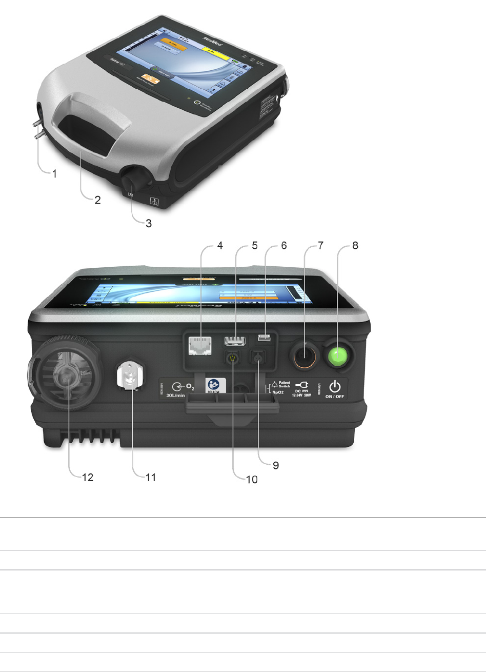
The Astral device
The following images describe the components of the Astral device.
Description
1
Adapter port
Can be fitted with single limb adapter, single limb leak adapter or double limb adapter (Astral 150 only).
2
Handle
3
Inspiratory port (to patient)
Provides an outlet for pressurised air to be delivered to the patient via the patient circuit. Includes FiO
2
sensor on the
Astral 150. The FiO
2
sensor is an optional accessory on the Astral 100.
4
Ethernet connector (service use only)
5
USB connector (for download to ResScan and connection of approved accessories)
6
Mini USB connector (for connection to RCM or RCMH)
The Astral device
English 5
Description
7
DC power inlet
8
Device on/off push button
9
SpO
2
Sensor connector
10
Remote alarm five pin connector
11
Low flow oxygen input (up to 30 L/min)
12
Air inlet (complete with hypoallergenic filter)
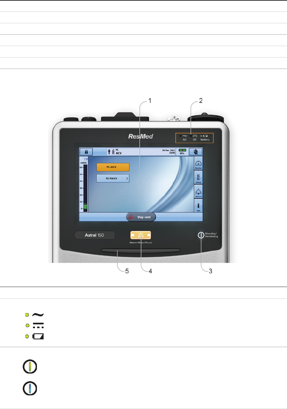
The Astral device interface
The interface of the Astral device comprises several different features described in the following image.
Description
1
Touch screen
2
Power source indicators
AC (mains power supply)
DC (external battery or car accessory adapter or RPSII)
Internal battery
3
Therapy on/off indicator
Device ready
Constant green display when the device is turned on but not ventilating.
Device ventilating
Flashes blue when the device is ventilating and the Ventilation LED setting is 'ON'.
Otherwise is 'OFF'.
The Astral device
6
Description
4
Alarm mute/reset button
Illuminates when an alarm is triggered and flashes when the sound is muted.
5
Alarm bar
Flashing red High priority alarm
Flashing yellow Medium priority alarm
Constant yellow Low priority alarm
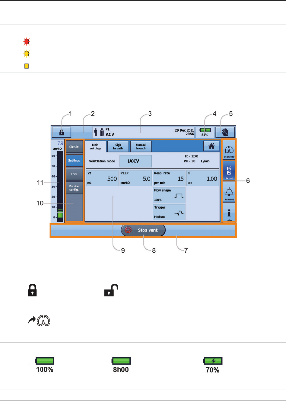
Touch screen
The main method of interacting with the Astral device is via the touch screen. The display on the touch
screen changes according to the function being performed.
Description
1
Clinical mode access button
Locked Unlocked
2
Manual breath button
only shown if enabled
3
Information bar
4
Internal battery indicator
5
Lock touch screen button
6
Menu bar
7
Bottom bar
The Astral device
English 7
Description
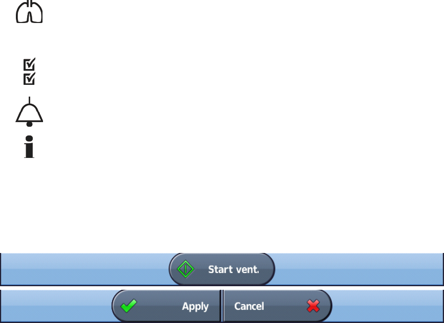
8
Start/Stop ventilation button
9
Main screen
10
Sub-menus
11
Pressure bar
Note: Do not access Clinical mode unless directed by a clinician.
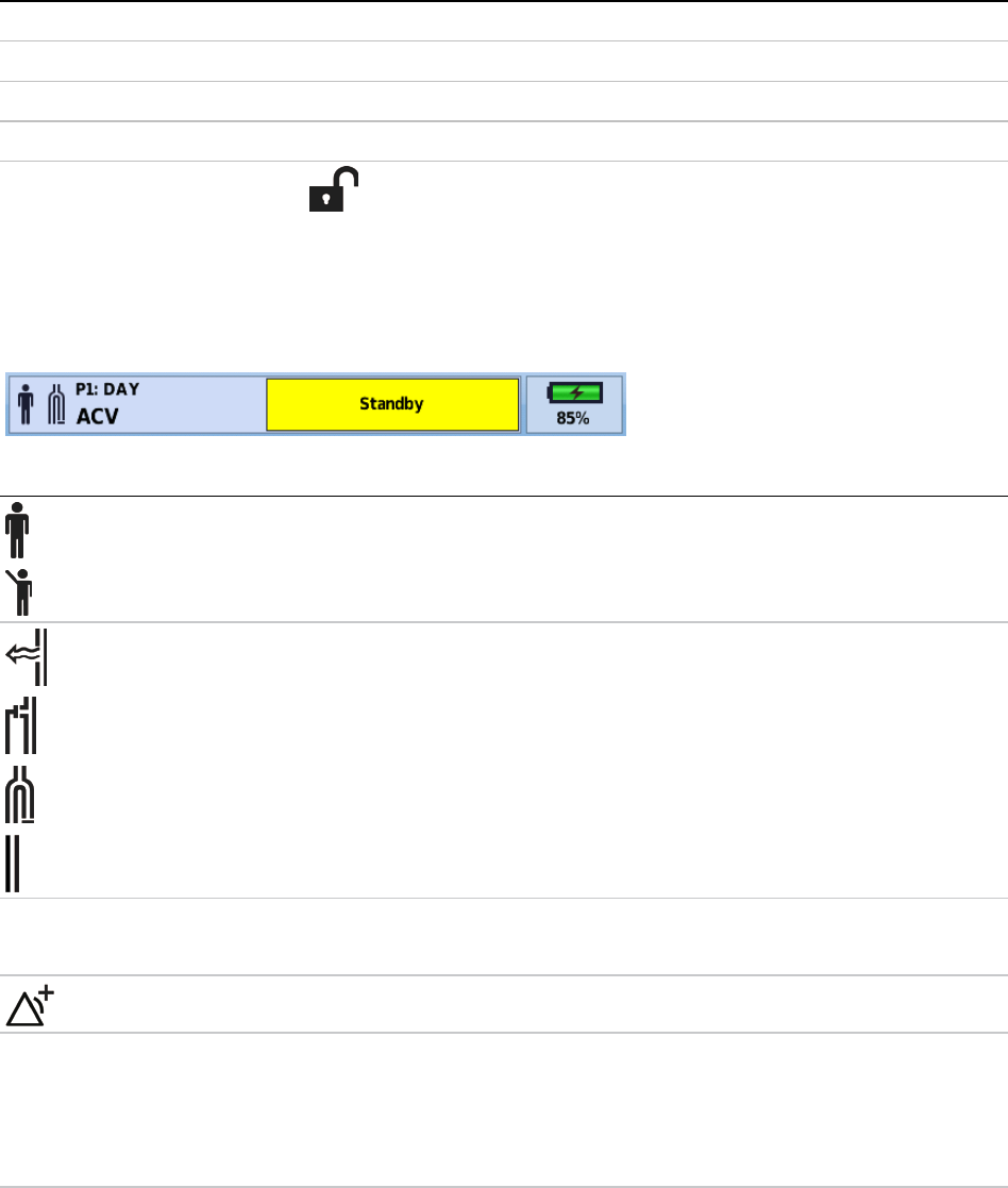
Information bar
The Information bar is displayed at the top of the touch screen. The Information bar displays the
operating status of the device, including patient type, current circuit configuration, programs, information
messages, ventilation status, alarms and power status.
Description
Patient type – Adult
Patient type – Pediatric
Circuit type – Single limb with intentional leak
Circuit type – Single limb with expiratory valve
Circuit type – Double limb
Circuit type – Mouthpiece
P1:DAY
(A)CV
Program number and program name
Ventilation mode
Multiple alarms are active simultaneously. The highest priority active alarm is displayed first.
Message
window
Will display alarms or information. Image above shows device in Standby. (Displayed when the device is powered
on but not ventilating). Date and time will be displayed when the device is ventilating and there are no active
alarms.
Information messages are displayed in blue text. If the device Alert tone setting is 'On', you will be alerted to new
information messages by a single beep.
The Astral device
8
Menu bar
The Menu bar provides access to the four main menus in the Astral device.
Monitors menu
View real-time patient data in either waveform or monitoring formats including pressure, flow, leak, tidal
volume, synchronisation and oximetry.
Setup menu
Configure and view ventilation therapy or device settings; and import/export data.
Alarms menu
Configure and view alarms including alarm volume.
Information summary menu
View therapy statistics, used hours, events, reminder and device information.
Bottom bar
The Bottom bar changes with the function of the device.
It can display buttons to Stop or Start ventilation and Apply or Cancel functions.
Main screen
The Main screen displays the monitoring data, ventilation and device controls. Each function is accessed
through the various menus and tabs.
The Astral device
English 9
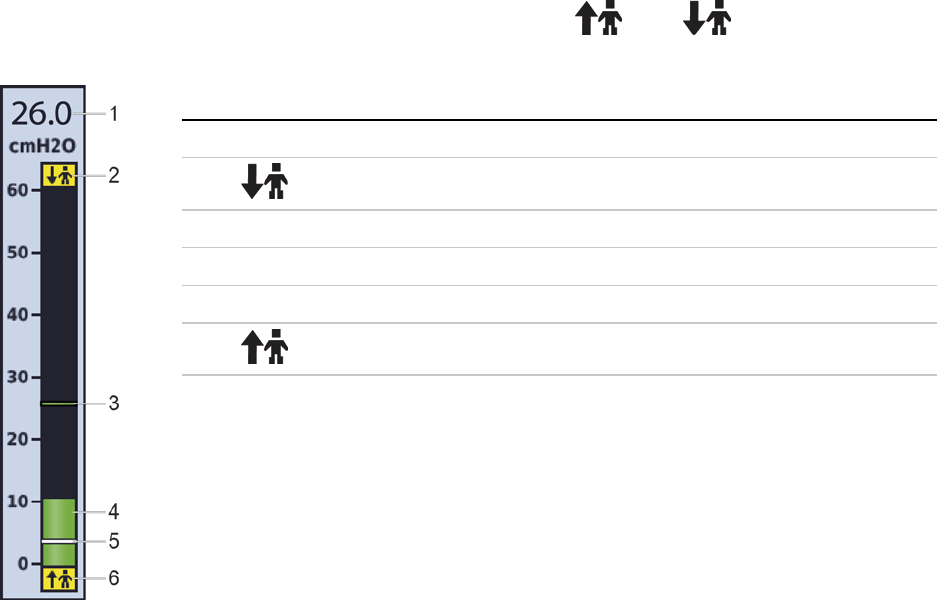
Pressure bar
The Pressure bar displays real-time therapy data while the Astral device is ventilating.
Patient pressure is shown as a bar graph. Peak inspiratory pressure is shown as a numerical value and
watermark. Spontaneously triggering and cycling is indicated by
and .
The example below displays the pressure bar when a patient is spontaneously breathing.
Description
1
Peak inspiratory pressure (PIP) value
2
Spontaneous cycled breath marker—indicates patient-cycled breath
3
Peak inspiratory pressure marker
4
Current pressure
5
Positive end expiratory pressure (PEEP) setting
6
Spontaneous triggered breath marker—indicates patient-triggered breath

Using the Astral device
10
Using the Astral device
WARNING
Make sure the area around the device is dry, clean and clear of bedding or clothes or other objects
that could block the air inlet. Blocking the cooling vents could lead to overheating of the device.
Blocking the air inlet could lead to patient injury.
CAUTION
•
To prevent possible damage to the ventilator, always secure it to its stand or place it on a flat,
stable surface. For mobile situations, ensure the Astral device is contained within its
mobility bag.
• Ensure the device is protected against water if used outdoors.
Using the Astral device for the first time
When using the Astral device for the first time, ResMed recommends you first perform a functional test.
A functional test will ensure the device is in proper working order before starting therapy. Information to
assist you in resolving any issues is available in the Troubleshooting (see page 64) section.
CAUTION
If any of the following checks fail, contact your Healthcare provider or ResMed for assistance.
To perform a functional test:
1. Turn off the device by pressing the power switch at the back of the device.
2. Check the condition of the device and accessories.
Inspect the device and all accessories. Damaged components should not be used.
3. Check the patient circuit setup.
Check the integrity of the patient circuit (device and provided accessories) and that all connections are secure.
4. Turn on the device and test alarms.
WARNING
If no alarm sounds, do not use the ventilator.
Press the power switch at the back of the device to turn on the device. Check that the alarm sounds
two test beeps and the LEDs for the alarm signal and the alarm mute/reset button flash. The device
is ready for use when the Patient Home screen is displayed.
5. Disconnect the device from the mains and external battery (if in use) so that the device is powered
by the internal battery. Check that the Battery Use alarm is displayed and the battery LED is on.
Note: If the charge state of the internal battery is too low an alarm occurs. Refer to Troubleshooting (see page
64).
6. Reconnect the external battery (if in use) and check that the LED for the DC power supply is lit. The
External DC Power Use alarm will be displayed and the Alarm LED will light.
7. Reconnect the device to mains power.
8. Check the pulse oximeter sensor (if in use).
Attach the accessories according to the set up descriptions. From the Monitoring menu, go to the
Monitoring screen. Check that the values for SpO
2
and pulse are displayed.
9. Check the oxygen connection (if in use). Check for damage to hoses or leaks. Check remaining
capacity of oxygen cylinders.
10. Perform a Learn Circuit.
Using the Astral device
English 11
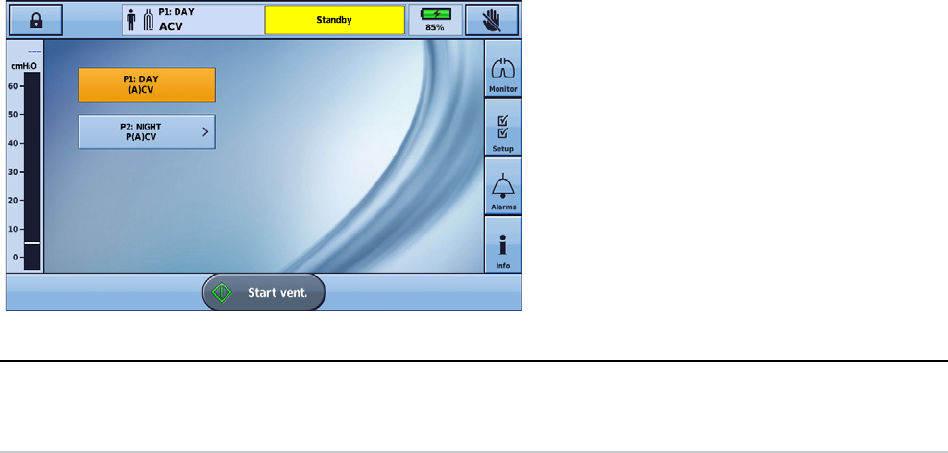
Powering on the device
To power on the Astral device, simply press the green power on/off button at the back of the device. The
device will perform a system check as shown on the main screen.
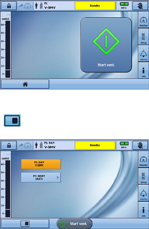
On completion of the system check, the Patient Home screen and active program is displayed.
Note: Settings configured in the active program will be used when ventilation is started.
Helpful hint!
If more than one program displays on the Patient Home screen, the active program will be highlighted
orange. For further information, refer to Programs (see page 19).
For information on powering the Astral device, refer to Power.
Powering off the device
The Astral device can only be powered off when ventilation is stopped.
Removing AC power does not power off the device. The device remains powered on internal battery.
Turning off the device must be done manually and must be performed before leaving the device
disconnected from AC power for any extended period of time. Failure to do so may result in battery
depletion and activation of alarms.
To power off the device, press the green on/off button at the back of the device and follow the on-screen
prompts. To ensure the device is fully powered down, touch the screen.
Note: While the device remains connected to external mains power, the internal battery continues to charge.
Using the Astral device
12
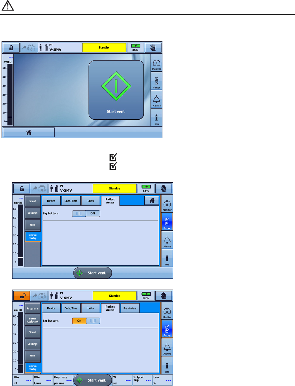
Enhanced access feature
The Astral device offers an enhanced access feature ('Big buttons' mode) to provide you with easier
usability and accessibility. The 'Big buttons' mode can be used to start and stop ventilation, as well as to
mute alarms.
WARNING
To prevent inadvertent alarm mute or reset, do not leave the patient in contact with the device
screen.
To enable the 'Big buttons' mode:
1. From the Main menu press Setup
. The Setup menu is displayed.
2. Select the Patient Access tab from the Device Config. menu.
3. Move the Big buttons slider to On.
Using the Astral device
English 13
Your enhanced access feature is now enabled.
With this feature enabled, it is possible to switch between ‘Big buttons’ mode and standard. Simply
select the Home button from left hand corner of the Bottom bar.
Your screen will return to standard button size and the Home icon will be replaced by the Big buttons
icon
.
To return to 'Big buttons' mode, simply select the Big buttons icon from the bottom bar.
Note: With the enhanced access feature enabled, your screen will return to 'Big buttons' mode once the screen
locks (after two minutes of inactivity).

Using the Astral device
14
Starting and stopping ventilation
Your clinician has set up one or more ventilation programs for your therapy. If more than one program
has been set up, follow the directions given by your clinician for when and how each program should be
used.
Note: If using the device for the first time, ResMed recommends performing a functional test before starting
ventilation. Refer to Using the Astral device for the first time (see page 10).
To start ventilation:
1. Press the green on/off button at the back of the device (if power is not already on).
2. Press
. Ventilation is started.
3. Add oxygen if required.
To stop ventilation:
Ventilation can be stopped at any time and from any screen.
1. If oxygen is connected, turn off the oxygen.
2. Press and hold
.
3. Release
when prompted.
4. Press Confirm. Ventilation is stopped.
Locking and unlocking the touch screen
The touch screen can be unlocked at any time.
To manually lock the touch screen, from the Information bar press
. When the touch screen is
locked the button is highlighted orange.
Unlocking the touch screen
Touch the screen anywhere and follow the on-screen prompts.
Using the Astral device
English 15
Navigating the menus
The Astral device has four menus accessible via the Menu bar. Each menu is further broken down into
various sub-menus.
Monitors menu
The Monitors menu allows you to view real-time ventilation data and is comprised of three sub-menus:
• Waveforms
• Monitoring
• Trends
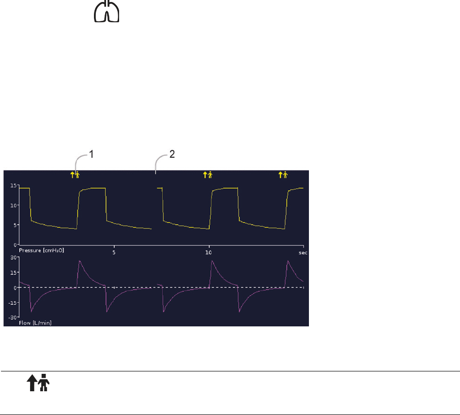
Waveforms
The Waveforms screen displays the last 15 seconds of patient airway pressure and flow in a graph. The
graph updates in real-time and when necessary the vertical axis will auto scale to accommodate changes
in amplitude.
Description
1
Spontaneous trigger breath marker—indicates patient-triggered breath.
2
Break in graph—indicates the current position and moves from left to right.
Using the Astral device
16
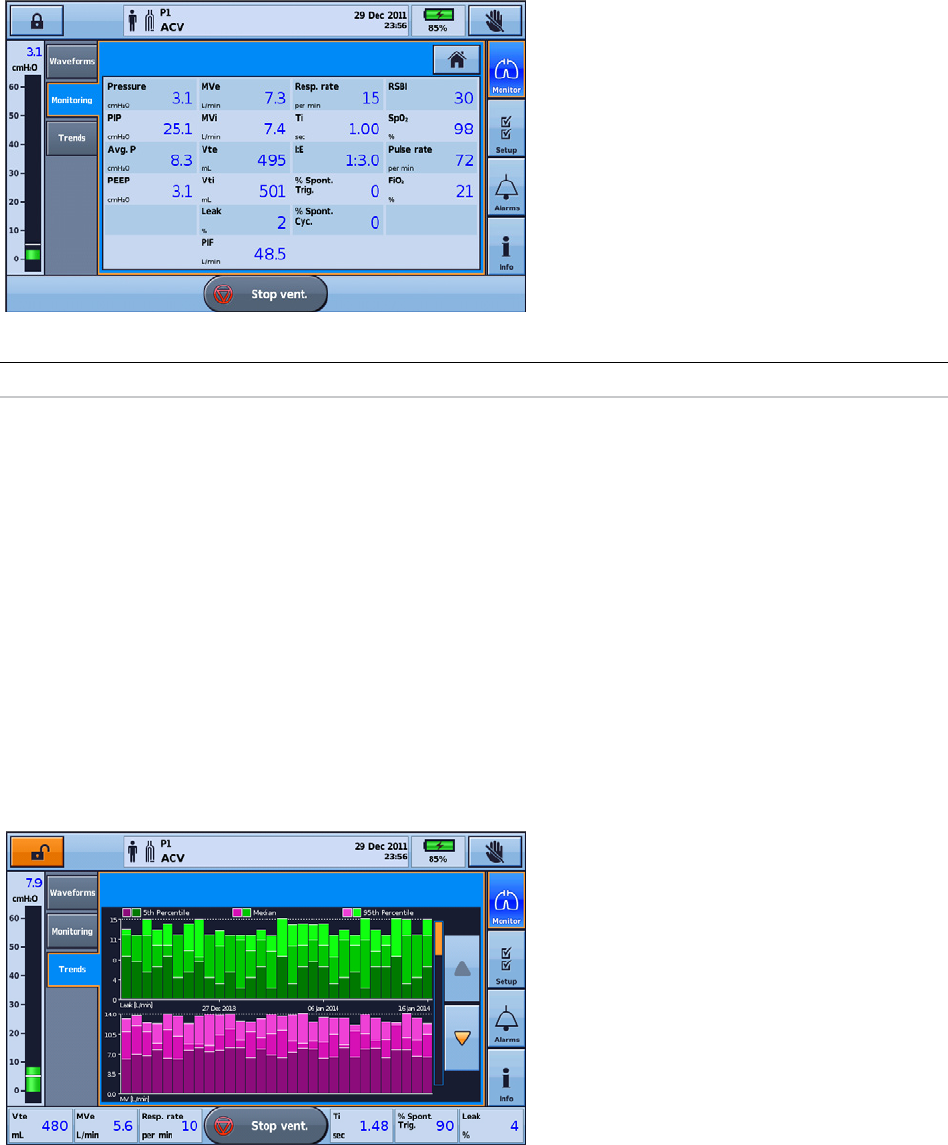
Monitoring screen
The Monitoring screen displays all measured parameters in numerical form.
Helpful hint!
Your care provider may ask you to access this screen and report values from time to time.
Trends screen
The Trends screen shows the 5th and 95th percentile values, as well as the median for the last 30 days
for each of the following parameters:
• Leak
• Minute ventilation
• Peak inspiratory pressure
• Tidal volume
• Respiratory rate
• Inspiratory time
• SpO
2
• Pulse rate
• FiO
2
• Alveolar ventilation.
Information is displayed as bar graphs, with two graphs per screen.
Use the up and down scroll arrows to cycle through the graphs.
Using the Astral device
English 17
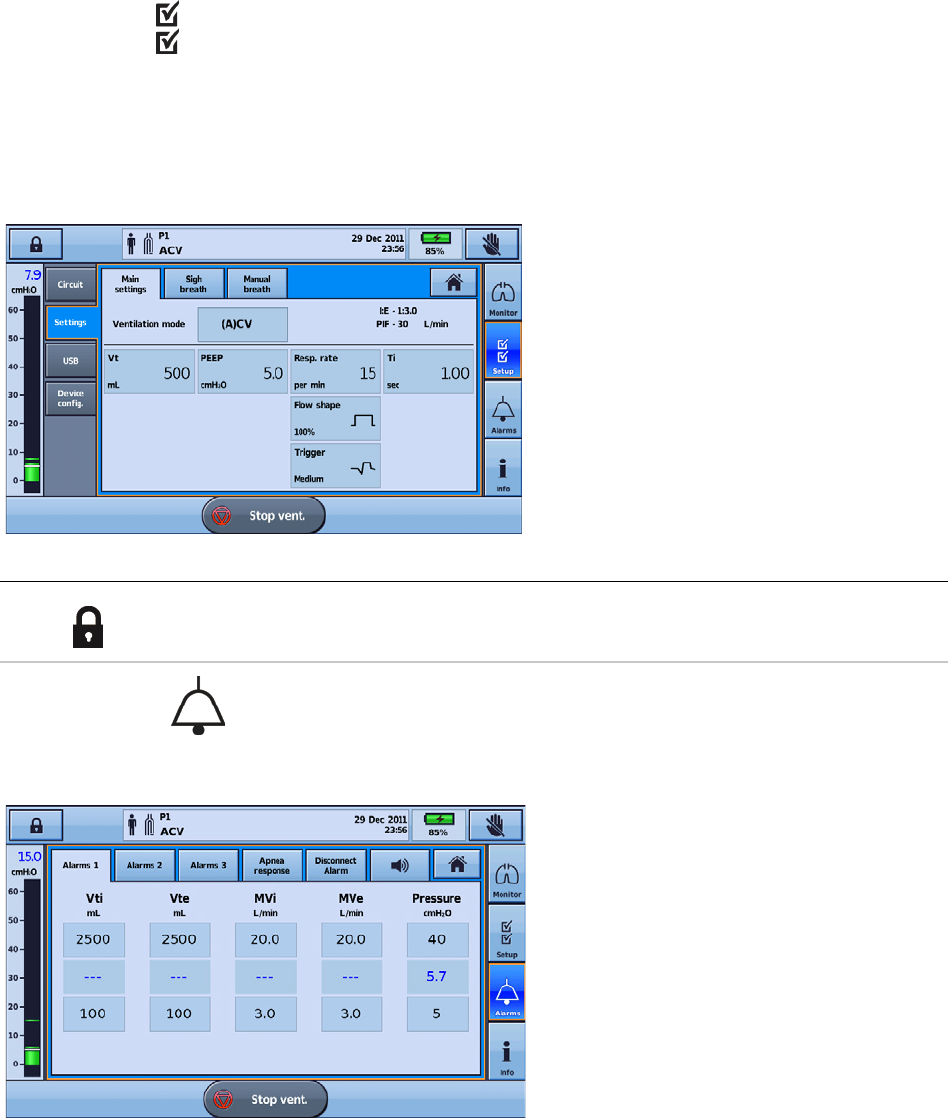
Setup menu
The Setup menu displays four different sub-menus:
• Circuit—to view the circuit
• Settings—to view the ventilation mode and access Manual Breath and Sigh Breath screens
• USB—to save patient data and import/export settings
• Device Config.—to change the device configuration.
Helpful hint!
Therapy and alarm settings can be viewed as 'read only' in Patient mode (ie, with Clinical mode
locked .
Alarms menu
The Alarms menu displays the individual thresholds for each alarm to trigger. Real-time values are
displayed between the upper and lower thresholds.
Using the Astral device
18
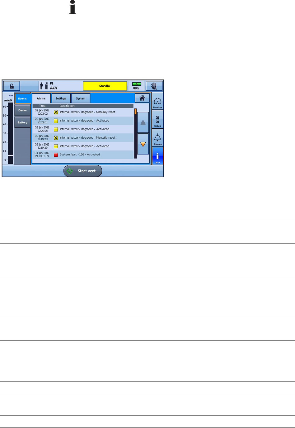
Information menu
The Information menu is comprised of three sub-menus:
• Events—all logged event activity that has taken place is displayed. A breakdown of specific alarms,
settings or system events can also be viewed.
• Device—information about the actual device is displayed, eg, Model and Serial numbers, Software
version, and Next service due date.
• Battery—information about the state of charge of the internal and external batteries when connected
including the combined total battery charge.
Device settings
The configurable settings are described in the following table.
Device setting Description
Alert Tone Sets alert tones to on or off.
Default: On
Alarm Volume Sets the volume level of the alarm system.
Settings from 1, 2, 3, 4 or 5.
Default: 3
Auto power off Automatically powers off the device after 15 minutes of inactivity.
Conditions: The device is in Ventilation standby mode (not ventilating), is being powered by the Internal
battery or an External battery and there are no active alarms.
Default: On
Display Brightness Sets the brightness of the screen from Auto with a selection of five different brightness levels.
Default: Auto
Backlight timeout
Allows the screen backlight to turn off (go black) if the screen has not been touched for two minutes or
more and there are no active alarms.
Setting to 'Off' will mean the screen back-light will be permanently on.
Default: On
Rotate Display Flips the current orientation of the display.
Device Vent LED Sets the status of the Ventilation active LED to On or Off during ventilation.
Default: On
Date Allows setting of the day, month and year of the current date.
Using the Astral device
English 19
Device setting Description
Time Allows setting of the hours and minutes of the current time.
Language Sets the current language of the device selected from the list of available languages.
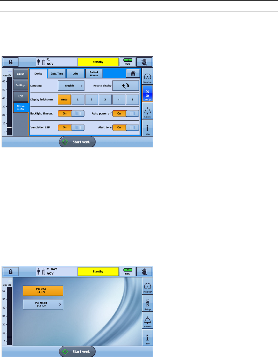
Adjusting device settings
Access adjustable device settings from the Setup menu and select Device Config.
The current active selections are highlighted in orange.
To change settings, simply select another of the available options. The revised setting is highlighted in
orange.
Programs
Programs on the Astral device can be configured by your clinician to provide you with alternate treatment
options. For example, a clinician can set up programs for sleeping versus daytime use, or for use during
exercise or physiotherapy. Programs allow for different circuit, ventilation and alarm settings.
The Astral device comes with one standard active program. Your clinician can configure up to three
additional programs (if available).
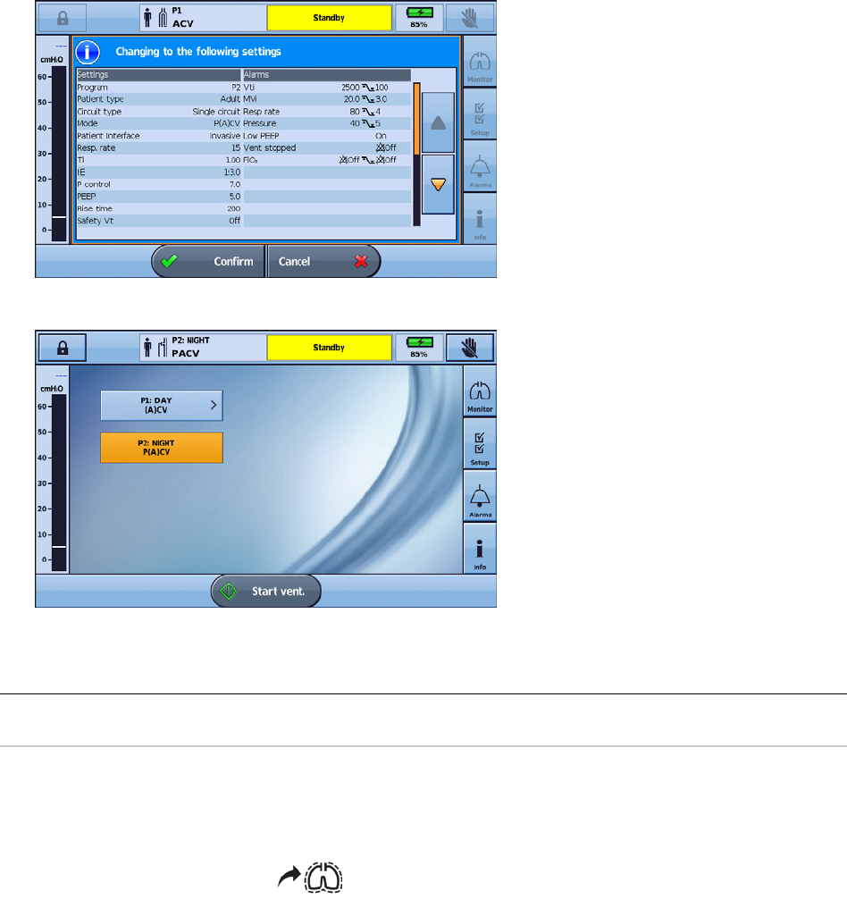
If any additional programs have been set up by your physician, they can be selected for use from the
Patient home screen. You can change between programs while the Astral device is delivering ventilation.
Changing between programs will cause ventilation and alarm settings to change, as configured by your
clinician.
Using the Astral device
20
To change between programs:
1. From the Patient home screen, select the program you want to use. A summary of the program
settings will be displayed.
2. Press Confirm to proceed with the change. The selected program becomes active and will be
highlighted orange.
Note: To change to a program with a different circuit type, you will need to stop ventilation. When you have changed
the circuit and the program, you can restart ventilation.
Helpful hint!
If more than one program has been set up, follow the directions given by your clinician for when and
how each program should be used.
Manual Breath feature
Your clinician may have enabled the Manual Breath feature. This feature allows a larger than normal
breath to be delivered.
To deliver a manual breath, press
.
Sigh Breath feature
Your clinician may have enabled the Sigh Breath feature. This feature delivers a larger 'sigh' breath at a
regular interval.
If configured, the Astral device will beep with a Sigh Alert prior to the Sigh Breath.
To turn the Sigh Alert on or off:
1. From the Setup menu, select Settings.
2. Set Sigh Alert on or off.
3. Press Apply to proceed with the change.
Assembling patient circuits
English 21
Travelling with the Astral device
WARNING
The Astral device should not be operated while in the Carry Bag. To ventilate while travelling, use
the Mobility Bag or SlimFit Mobility bag.
When travelling with the Astral device:
• The Astral device should always be packed in its carry bag when not in use to prevent damage to the
device.
• The carry bag is for carry-on luggage only. The carry bag will not protect the Astral device if it is put
through checked baggage.
• For your convenience at security stations, it may be helpful to keep a printed copy of the user guide
in the Astral carry bag to help security personnel understand the device and refer them to the
following statement.
• ResMed confirms that the Astral device meets the Federal Aviation Administration (FAA)
requirements (RTCA/DO-160, section 21, category M) for all phases of air travel.
• For power management tips, refer to Power management (see page 41).
Assembling patient circuits
Circuit options
The Astral device supports a range of circuits (the device and accessories assembled together) to suit
individual patient needs. The device uses interchangeable circuit adapters.
The following table may assist in selecting suitable circuits and settings for different patient types:
Tidal volume range Recommended patient type setting Suitable circuit diameters
50 mL to 300 mL Pediatric 10 mm, 15 mm or 22 mm
> 300 mL Adult 15 mm or 22 mm
WARNING
•
Use a double limb circuit for direct measurement of exhaled volumes. In this configuration, the
expired volume is returned to the ventilator for independent measurement. (Astral 150 only)
• The Astral device does not support monitoring of exhaled volumes when used with a single
limb circuit with expiratory valve.
• The patient circuit should be arranged so as not to restrict movement or pose a strangulation
risk.
• Only use circuit components that comply with the relevant safety standards including
ISO 5356-1 and ISO 5367.
CAUTION
For pediatric use, ensure that the patient circuit type fits and is suitable for use with a child. Use a
pediatric patient type for patients that weigh less than 23 kg and normally require less than 300 mL
tidal volume.
Assembling patient circuits
22
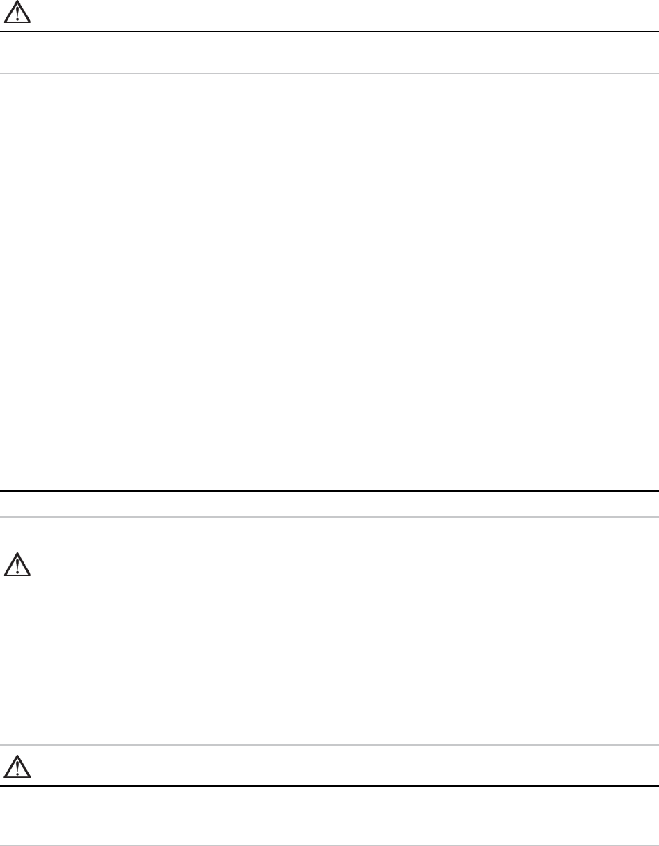
There are three circuit adapters:
Adapter
For use with
1 Single limb leak
Single limb circuit with intentional leak or mouthpiece circuit
2 Single limb
Single limb circuit with expiratory valve (expiratory valve integrated into the circuit)
3
Double limb
(Astral 150 only)
Double limb circuit (expiratory valve integrated into the adapter) OR single limb circuit with
intentional leak or mouthpiece circuit
A Learn Circuit should be performed after any change of circuit. Astral will provide accurate therapy as long as the Learn Circuit
is completed. Refer to Learn Circuit (see page 29) for further information.
WARNING
The measurement of patient exhaled gas volume may be affected by leak.
Helpful hint!
Only use adapters and circuits as directed by your clinician.
Assembling patient circuits
English 23
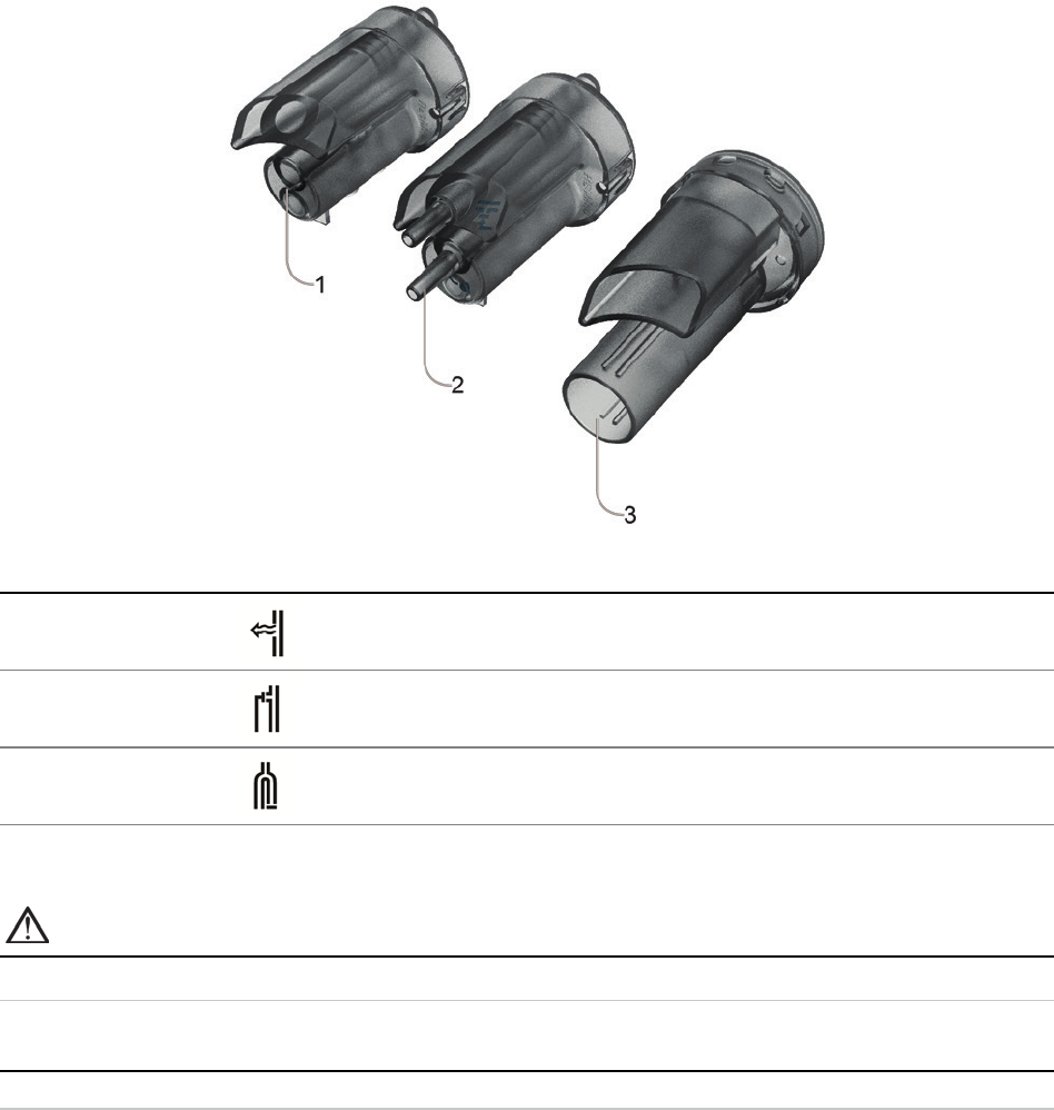
Fitting the circuit adapter
Before connecting the patient circuit, the adapter specific to the required circuit type must be fitted.
To fit the adapter:
1. Turn over the device and place on a soft surface (to protect the LCD screen).
2. Press and hold the eject button. Pull the cover out towards you.
3. Lift the adapter out of the socket.
4. Replace with the new adapter, ensuring it sits firmly in the socket.
5. Place the cover over the enclosure, ensuring the runners on the device and the cover are aligned.
Slide the cover back into place until the latch clicks.
Connecting a single limb circuit with intentional leak
An intentional leak may be provided in-line using the ResMed Leak Valve or via an integrated mask vent.
When using a circuit with intentional leak, estimation of the patient respiratory flow is enhanced by
ResMed's automatic leak management feature Vsync. Vsync technology allows the device to estimate
the patient respiratory flow and tidal volume in the presence of unintentional leak.
WARNING
• At low pressures, the flow through the mask vents may be inadequate to clear all exhaled
gases, and some rebreathing may occur when using a single limb circuit with intentional leak.
• Ensure the vent holes at the mask or at the ResMed Leak Valve are unobstructed. Ensure the
area around the vent holes is clear of bedding, clothes, or other objects and that the vents
holes are not directed towards the patient.
To connect a single limb circuit with intentional leak:
1. Check the device is fitted with the single limb leak adapter. Otherwise, change the adapter.
Note: The Astral 150 can also support a single limb circuit with intentional leak using a double limb adapter.
2. Connect the inspiratory limb to the inspiratory port.
3. Attach any required circuit accessories (eg, humidifier or filter).
4. Select the circuit type and perform a Learn Circuit.
Assembling patient circuits
24
5. If using a non-vented mask or tracheostomy connector, attach a ResMed Leak Valve to the free end
of the air tubing ensuring that the Leak Valve is as close as possible to the patient.
6. Attach the patient interface (eg, mask) to the Leak valve or the free end of the air tubing as
appropriate and adjust the mask type setting on the Astral device.
Connecting a single limb circuit for invasive use
CAUTION
Always set up the ResMed Leak Valve in the breathing circuit with the arrows and the symbol
pointing in the direction of air flow from the Astral device to the patient.
For invasive ventilation, since the patient's upper respiratory system is bypassed by an artificial airway
device (for example endotracheal or tracheostomy tube) humidification of the inspired gas is required to
prevent lung injury.
Assembling patient circuits
English 25
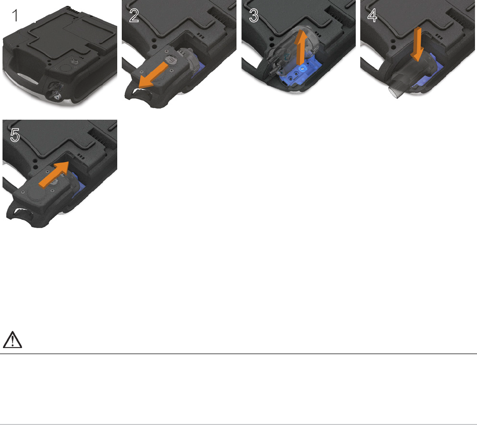
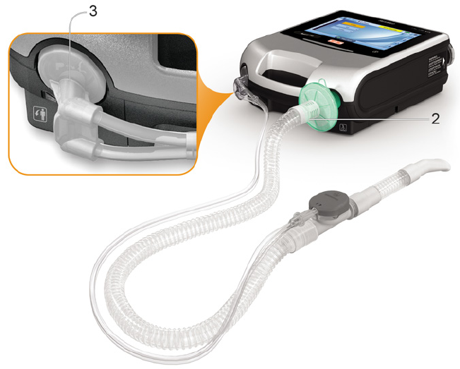
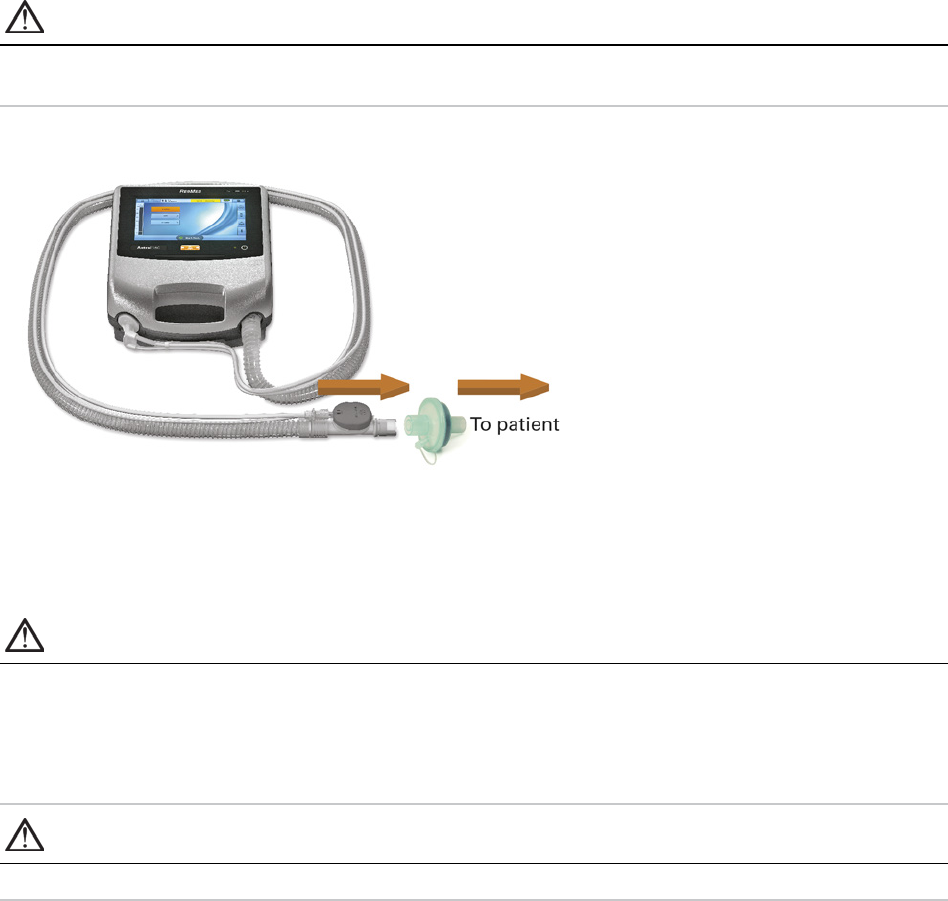
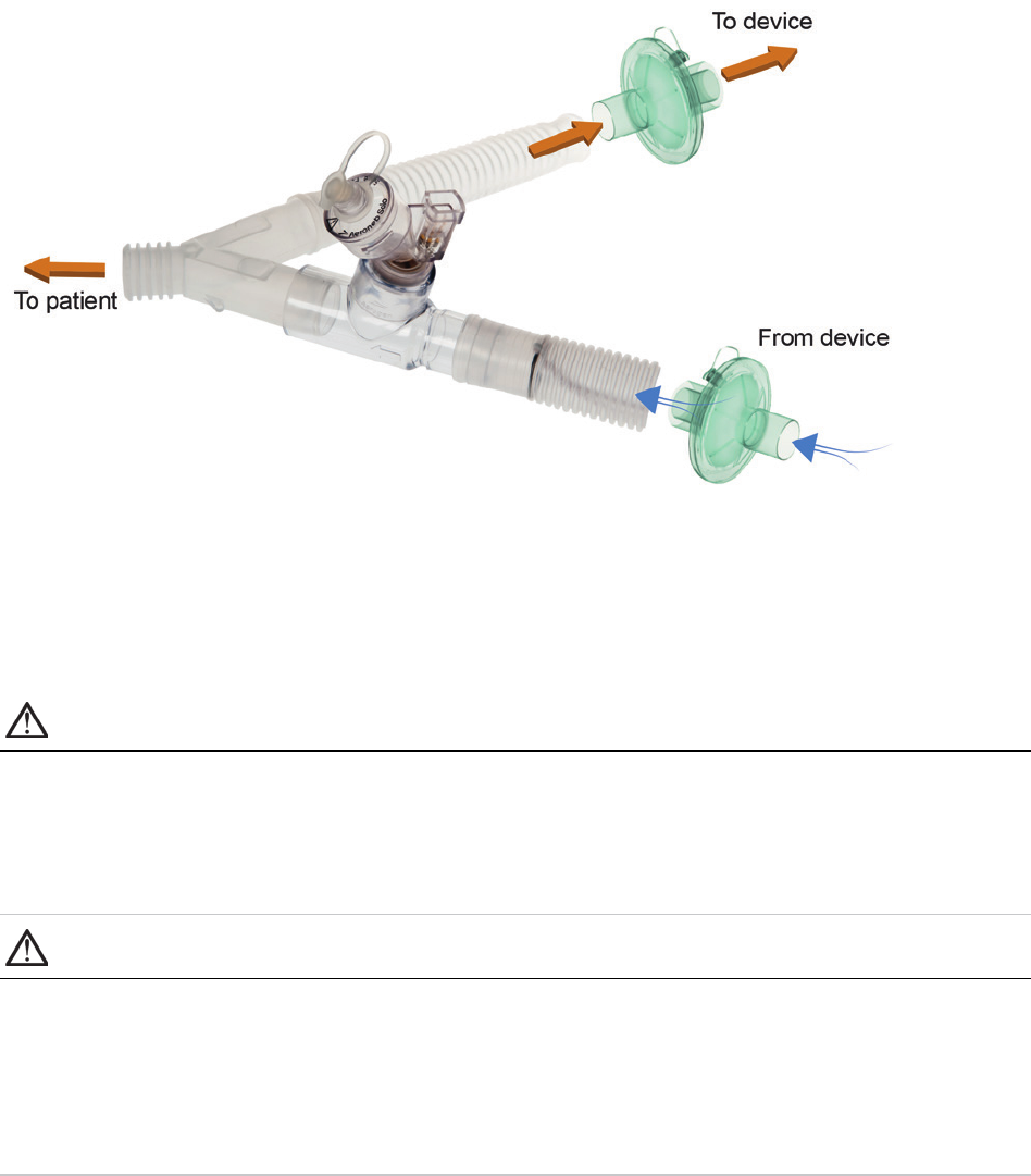
Connecting a single limb circuit with expiratory valve
To enable fast and accurate connection, use an Astral Quick Connect Single Limb Circuit. This custom
accessory with its integrated proximal pressure sensor and expiratory valve control line, is designed
specifically for use with Astral ventilators.
To connect an Astral 'Quick Connect' Single Limb Circuit with expiratory valve:
1. Check the device is equipped with the single limb adapter (otherwise change the adapter).
2. Connect the air tubing to the inspiratory port on the device.
3. Attach the Astral Quick Connect circuit to the single limb adapter on the device (see diagram below).
4. Attach any required circuit accessories (eg, humidifier or filter).
5. Select the circuit type and perform a Learn Circuit.
6. Attach a patient interface (eg, mask) to the connector on the pneumatic valve.
Assembling patient circuits
26
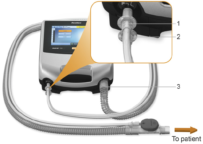
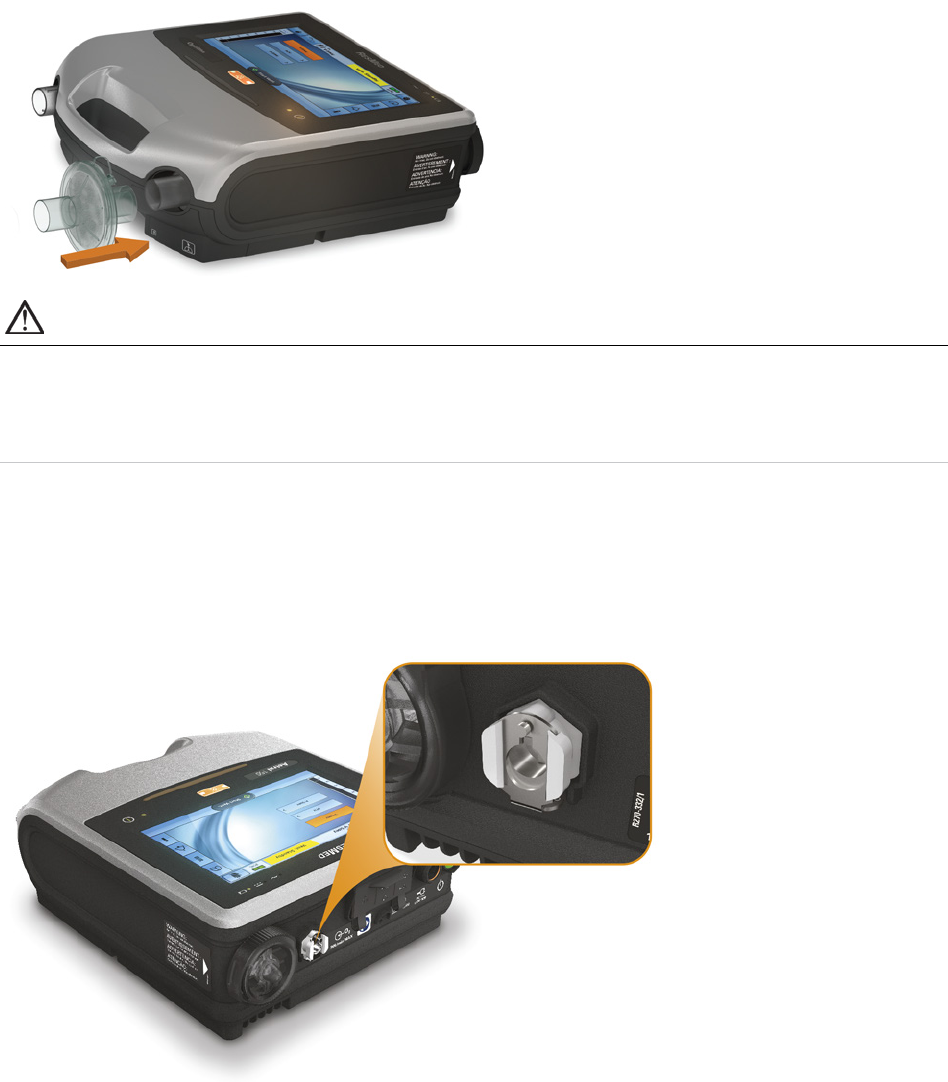
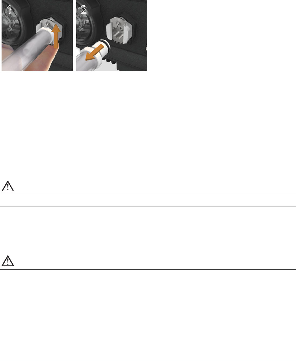
To connect a standard single limb valved circuit to the Astral:
1. Connect the Proximal pressure line to the upper connector of the Astral device single limb adapter.
2. Connect the PEEP control line to the lower connector of the Astral device single limb adapter.
3. Connect the air tubing to the inspiratory port of the device.
4. Attach any required circuit accessories (eg, humidifier or filter).
5. Select the circuit type and perform a Learn Circuit.
6. Attach a patient interface (eg, mask) to the connector on the pneumatic valve.

Assembling patient circuits
English 27
Connecting a double limb circuit (Astral 150 only)
The Astral device measures exhaled air flowing through the double limb circuit adapter. This enables
patient-exhaled tidal volume to be accurately measured and monitored.
To connect a double limb circuit:
1. Ensure the device is fitted with the double limb adapter (otherwise change the adapter).
2. Connect the ends of the air tubing to the inspiratory and adapter ports on the device.
3. Attach any required circuit accessories (eg, humidifier or filter).
4. Select the circuit type and perform a Learn Circuit.
5. Attach a patient interface (eg, mask) to the end of the air tubing.
Assembling patient circuits
28
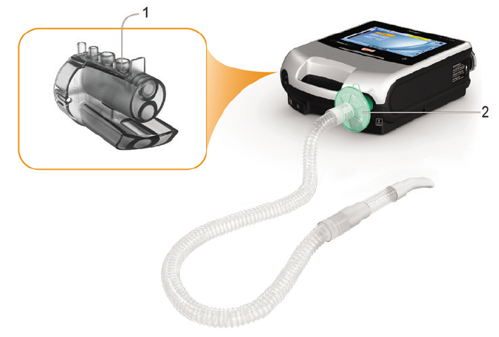
Connecting a mouthpiece circuit
The mouthpiece circuit is a single limb circuit with no expiratory valve or intentional leak. This circuit is
not intended to support continuous exhalation into the circuit. For patients that may prefer continuous
exhalation into the circuit, a circuit with expiratory valve or intentional leak should be considered.
To connect a mouthpiece circuit:
1. Check the device is fitted with a single limb leak adapter. Otherwise, change the adapter.
Note: The Astral 150 can also support mouthpiece circuit using a double limb adapter.
2. Connect the inspiratory limb to the inspiratory port.
3. Attach any required circuit accessories (eg, filter).
4. Select the circuit type and perform a Learn Circuit.
5. Attach the patient interface (eg, mouthpiece) to the free end of the air tubing as appropriate.
Assembling patient circuits
English 29
Learn Circuit
In order to support a wide range of circuit configurations and accessories, the Astral device provides a
Learn Circuit function to determine the characteristics of the circuit. As part of the Learn Circuit
functionality the Astral performs a device self-test and a calibration of the FiO
2
sensor (if installed).
CAUTION
To ensure optimum and accurate performance, it is recommended that the Learn Circuit function
be performed with every change of circuit configuration and at regular intervals not less than once
every three months.
Do not connect patient interfaces prior to performing the Learn Circuit. Patient interfaces include any
components placed after the single circuit's expiratory valve or exhalation port, or double limb circuit's 'Y'
piece (eg, HMEF, catheter mount, mask, tracheostomy tube).
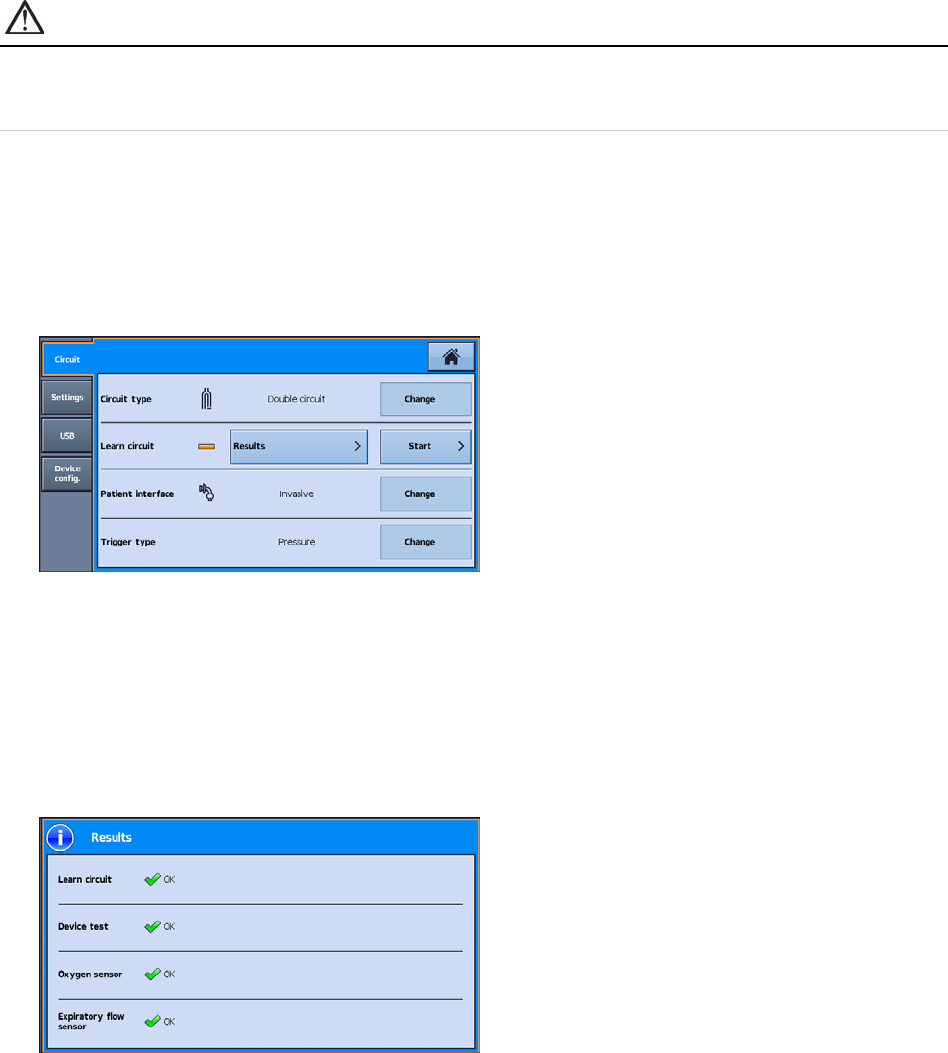
To perform a Learn Circuit:
1. From the Setup main menu, select the Circuit sub-menu.
2. Press Start and follow the on-screen prompts.
Note: Trigger type sets whether a pressure-based or flow-based trigger threshold is used when a Double circuit
is selected.
The prompts will guide you through a number of steps including:
- With the patient interface disconnected from the patient connection port, the Astral device will
characterise the impedance of the inspiratory path.
- With the patient connection port sealed, the Astral device will characterise the total circuit
compliance, and then the impedance of the expiratory path.
After completing these steps, a test result screen is displayed. You can access this Results screen
later using the Results button in the Circuit setting up screen.

Assembling patient circuits
30
The following icons are used to report the Learn Circuit results:
Learn Circuit Results
Icon Description
Learn Circuit completed
Learn Circuit not tested. Default circuit characteristics will be applied. Accuracy of control and monitoring may not be
met. Ensure that ventilation and alarms are effective before proceeding further.
Learn Circuit completed. Circuit resistance is high. The device will use the learned circuit characteristics. Accuracy of
control and monitoring may not be met.
If your clinician has configured your device with this circuit test result, then you may continue under the instruction of
your clinician. However, if this is the first time you have seen this result, check with you clinician whether it is
safe for you use this circuit configuration.
Learn Circuit has failed. Default circuit characteristics will be applied.
Below are general steps to resolve the Learn Circuit issue. Refer to Learn Circuit Troubleshooting (see page 68) for
suggested actions on the error code.
1. Inspect the circuit and proximal lines for disconnection or excessive leak.
2. Check that the circuit is correctly connected and matches the selected circuit type.
3. Check that the correct circuit adaptor is installed for the selected circuit type.
4. Check the module, the blue membrane and sensor are pressed all the way in and sit flush with the enclosure.
Accuracy of control and monitoring will be degraded. Ensure that ventilation and alarms are effective before
proceeding further.
Device Test Results
Icon Description
Device Test has passed.
Device Test has not been run. This only occurs on setting up a new therapy program.
Device Test has failed. Learn Circuit cannot be run.
Below are general steps to resolve the Learn Circuit issue. Refer to Learn Circuit Troubleshooting (see page 68) for
suggested actions on the error code.
1. Inspect the air inlet for foreign materials.
2. Inspect the air filter and replace it, if necessary. Refer to Cleaning and maintenance (see page 60) for further
instructions.
3. Remove the expiratory module and inspect the module and blue membrane for any foreign materials.
4. Re-install the module, ensuring that it is securely in place.
5. Repeat Learn Circuit. If problem persists, refer to Learn Circuit Troubleshooting (see page 68) for suggested
actions on the error code.
If you choose to proceed with ventilation, accuracy of control and monitoring will be degraded. Ensure that ventilation
and alarms are effective before proceeding further.

Assembling patient circuits
English 31
Oxygen (FiO
2
) Sensor Results
Icon Description
Oxygen sensor calibration has passed.
Oxygen sensor not tested or not installed.
1. If your device was supplied without an oxygen sensor, ignore this message and proceed with therapy.
2. If possible, check that the oxygen sensor is securely attached as described in Replacing the oxygen sensor.
3. Repeat Learn Circuit. If the oxygen sensor is still not detected, return the device for servicing by an authorised
ResMed Service Centre.
Oxygen sensor calibration has failed.
Below are general steps to resolve the oxygen sensor calibration issue. Refer to Learn Circuit Troubleshooting (see
page 68) for suggested actions on the error code.
1. If possible, replace the oxygen sensor as described in Replacing the oxygen sensor.
2. Repeat Learn Circuit. If problem persists, return the device for servicing by an authorised ResMed Service Centre.
If you choose to proceed with ventilation, FiO
2
alarms will be disabled. An alternate method for monitoring FiO
2
is
required.
Expiratory Flow Sensor Results
Icon Description
Expiratory flow sensor calibration has passed.
Expiratory flow sensor not tested or not installed.
Expiratory flow sensor calibration has failed.
Below are general steps to resolve the expiratory flow sensor calibration issue. Refer to Learn Circuit Troubleshooting
(see page 68) for suggested actions on the error code.
1. Remove the adapter, seal, and expiratory flow sensor.
2. Inspect the module, seal, and flow sensor for any foreign materials.
3. Re-install the module and flow sensor, ensuring that it is securely in place.
4. If possible, replace the expiratory flow sensor as described in Replacing the expiratory flow sensor.
5. Repeat Learn Circuit. If problem persists, return the device for servicing by an authorised ResMed Service Centre.
If you choose to proceed with ventilation, check Vte and MVe alarms are effective.

Accessories
32
Accessories
For a full list of accessories, see Ventilation accessories on www.resmed.com under the Products page.
If you do not have internet access, please contact your ResMed representative.
WARNING
Before using any accessory, always read the accompanying User Guide.
Helpful hint!
Only use accessories as directed by your clinician. Replace accessories according to the manufacturer's
instructions.
Power accessories
WARNING
• The Astral device should only be used with accessories recommended by ResMed. Connection
of other accessories could result in patient injury or damage to the device.
• Connecting the Astral device to the battery of a battery-powered wheelchair may affect the
device performance and may result in patient harm.
The Astral device can be connected to a range of accessories as follows:
• Astral External Battery
• ResMed Power Station II
• Astral DC adapter
• ResMed Remote Alarm II
• Pulse Oximeter.
Optional accessories
The Astral device can be used with a range of optional accessories as follows:
• Astral Mobility Bag
• Astral SlimFit Mobility Bag
• ResMed Homecare Stand
• Astral Table Stand
• Aerogen
®
nebuliser
• ResMed Connectivity Module (RCM)
• ResMed Connectivity Module for Hospital (RCMH).
Note: Some accessories may not be available in all regions.
Attaching patient circuit accessories
WARNING
• Adding or removing circuit components can adversely affect ventilation performance. ResMed
recommends performing a Learn circuit every time an accessory or component is added to or
removed from the patient circuit. If the circuit configuration is changed, the Disconnection
Alarm needs to be checked for correct operation.
• Do not use electrically conductive or anti-static air tubing.
Accessories
English 33
Attaching a humidifier
A humidifier or HME is recommended for use with the Astral device.
WARNING
• For invasive ventilation, since the patient's upper respiratory system is bypassed by an artificial
airway device (for example endotracheal or tracheostomy tube) humidification of the inspired
gas is required to prevent lung injury.
• Always place the humidifier on a level surface below the level of the device and the patient to
prevent the mask and tubing filling with water.
• Only use humidifiers that comply with the relevant safety standards, including ISO 8185 and
set up the humidifier according to the manufacturer's instructions.
• Monitor the air tubing for water condensation and / or spillage from the humidifier. Use
appropriate precautions to prevent water in the circuit transferring to the patient (eg, a water
trap).
For non-invasive ventilation, for patient experiencing dryness of the nose, throat or mouth, humidification
of the inspired gas will prevent subsequent irritation and discomfort.
CAUTION
Make sure that the water tub is empty and thoroughly dried before transporting the humidifier.
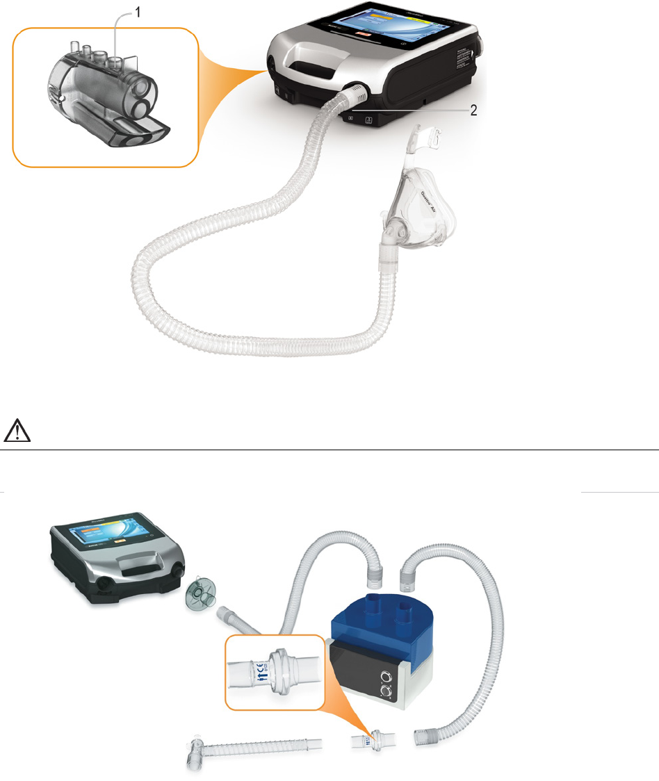
To attach a humidifier to a patient circuit:
1. Connect a length of air tubing to the inspiratory port on the device.
2. Connect the other end of the air tubing to the inlet port on the humidifier.
3. Connect the patient circuit to the outlet port on the humidifier.
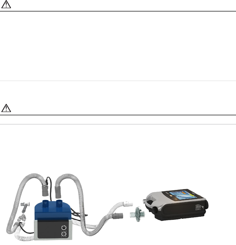
The image below shows proper use of a humidifier in combination with a double limb circuit.
When using heated humidification with a double limb circuit, condensation may form in the expiratory
flow sensor if the air is cooled to below its dew point. Condensation may also form in the patient circuit
and is most likely to form at high humidity settings and low ambient temperatures.
Condensation forming in the expiratory flow sensor may cause a loss of expiratory flow measurement
and compromised therapy (ie, auto-triggering, increased PEEP and activation of the leak alarm.
To prevent condensation at the Expiratory flow sensor, always follow the humidifier manufacturer's
instructions on how to prevent condensation and regularly check the patient circuit for condensation.
To ensure accurate therapy, Astral's Learn Circuit function should be performed prior to filling the water
tub.
Accessories
34
Attaching a Heat Moisture Exchange (HME)
HME's are passive humidification systems that retain heat and moisture from the patient's exhaled
gases via an internal membrane. An HME should not be used with active humidification. An HME can
be used with the Astral device with a double limb circuit or single limb circuit with integrated valve.
WARNING
Only use HMEs that comply with the relevant safety standards, including ISO 9360-1 and
ISO 9360-2.
Place the HME between the patient end of the circuit and the patient interface.
Do not connect patient interfaces prior to performing the Learn Circuit. Patient interfaces include any
components placed after the single circuit's expiratory valve or exhalation port, or double limb circuit's 'Y'
piece (eg, HMEF, catheter mount, mask, tracheostomy tube).
Attaching an antibacterial filter
WARNING
• Regularly check the antibacterial filter and expiratory valve for signs of moisture or other
contaminants, particularly during nebulisation or humidification. Failure to do so could result
in increased breathing system resistance and/or inaccuracies in expired gas measurement.
• Only use antibacterial filters that comply with the relevant safety standards, including
ISO 23328-1 and ISO 23328-2.
CAUTION
The antibacterial filter must be used and replaced according to the manufacturer's specifications.
Accessories
English 35
To attach an antibacterial filter:
1. Fit the antibacterial filter to the inspiratory port of the device.
2. Connect the air tubing to the other side of the filter.
3. Perform the Learn Circuit function.
4. Attach the patient interface to the free end of the air tubing.
WARNING
• To prevent the risk of cross-contamination, an antibacterial filter is mandatory if the device is to
be used on multiple patients.
• The expiratory module, internal antibacterial filter, expiratory flow sensor and blue membrane
come into contact with exhaled gases but do not form part of the inspiratory pathway.
Adding supplemental oxygen
Oxygen may be prescribed by your clinician.
The Astral device is designed to be compatible with levels of supplemental oxygen up to 30 L/min.
At a fixed rate of supplemental oxygen flow, the inhaled oxygen concentration will vary depending on the
Ventilation mode and settings, patient breathing pattern, mask selection, and leak rate.

Accessories
36
WARNING
•
Use only medical grade oxygen sources.
• Always ensure that the device is ventilating before the oxygen supply is turned on.
• Oxygen flow must be turned off when the device is not ventilating so that oxygen does not
accumulate within the device enclosure. Explanation: Accumulation of oxygen presents a risk
of fire. This applies to most types of ventilators.
• Oxygen supports combustion. Oxygen must not be used while smoking or in the presence of
an open flame. Only use oxygen in well-ventilated rooms.
• Supplemental oxygen must be added into Astral’s oxygen inlet at the rear of the device.
Adding oxygen elsewhere, ie, into the breathing system via a side port or at the mask, has
potential to impair triggering and accuracy of therapy/monitoring and impair alarms (eg, High
Leak alarm, Non-vented mask alarm)
• The patient circuit and the oxygen source must be kept at a minimum distance of 2 m away
from any sources of ignition.
• Monitor supplemental oxygen using the integrated FiO
2
sensor and alarms or use an external
O2 monitor compliant with ISO 80601-2-55.
• When operating Astral in its mobility bag do not add more than 6 L/min of supplemental
oxygen.
• Astral is not designed for use with heliox, nitric oxide or anesthetic gases.
• Do not position the Astral device on its side as this may affect FiO
2
monitoring accuracy.
To add supplemental oxygen:
1. Unlock the low flow oxygen inlet at the rear of the device by pushing up on the locking clip.
2. Insert one end of the oxygen supply tubing into the oxygen port connector. The tubing will
automatically lock into place.
3. Attach the other end of the oxygen supply tubing to the oxygen supply.
4. Start ventilation
5. Turn on oxygen and adjust (at the oxygen supply) to the prescribed flow rate or FiO
2
level.
Supplemental oxygen can also be added from an oxygen bottle however, a flow regulator must be fitted
to ensure the delivered oxygen remains at or below 30 L/min.
Before you remove supplemental oxygen from the device, ensure the Oxygen supply has been turned
off.
Accessories
English 37
To remove supplemental oxygen:
1. Unlock the low flow oxygen inlet at the rear of the device by pushing up on the locking clip.
2. Remove the oxygen port connector from the low flow oxygen inlet.
Monitoring delivered oxygen
The FiO
2
sensor is a standard inclusion on the Astral 150 and an optional accessory on the Astral 100.
The sensor measures the average of percentage of oxygen delivered to the circuit through the inspiratory
limb.
Prior to using the FiO
2
monitor, a Learn Circuit needs to be performed to calibrate the sensor. Repeat the
calibration at regular intervals at least once every three months.
Note: It may take up to 30 minutes for the FiO
2
sensor readings to meet the specified accuracy after
powering on the device from off state or when all power source indicators are off.
The FiO
2
sensor performance can be adversely affected by relative humidity, condensation on the sensor
or unknown gas mixtures.
WARNING
Do not position the Astral device on its side as this may affect FiO
2
monitoring accuracy.
Attaching a nebuliser
If required, a nebuliser can be used in conjunction with the Astral device. ResMed recommends
Aerogen
®
nebuliser products—designed to operate in-line with standard ventilator circuits and
mechanical ventilators without changing ventilator parameters or interrupting ventilation.
WARNING
•
Always connect antibacterial filters to both the inspiratory port and the expiratory inlet of the
Astral device to protect the device.
• Regularly check the antibacterial filter and expiratory valve for signs of moisture or other
contaminants, particularly during nebulisation or humidification. Failure to do so could result
in increased breathing system resistance and/or inaccuracies in expired gas measurement.
• Only operate the nebuliser when the device is ventilating. If ventilation is stopped, switch off
the nebuliser.
• Use of a gas jet nebuliser may affect ventilator accuracy. Monitor the patient and compensate
for the gas volume introduced by the gas jet nebuliser as appropriate.
• For full details on using a nebuliser, see the User Guide that comes with that device.
Accessories
38
Connect the nebuliser unit with a T-piece into the inspiratory limb of the breathing circuit before the
patient. If one of the Aerogen nebuliser models is being used (ie, Aeroneb Solo and Aeroneb Pro), it can
be powered via the USB connector at the rear of the Astral device, or the Aerogen USB AC/DC adapter.
Pictured above: Aeroneb
®
Solo in-line.
For full instructions for use, please consult the Aeroneb Solo System Instruction Manual.
Attaching other accessories
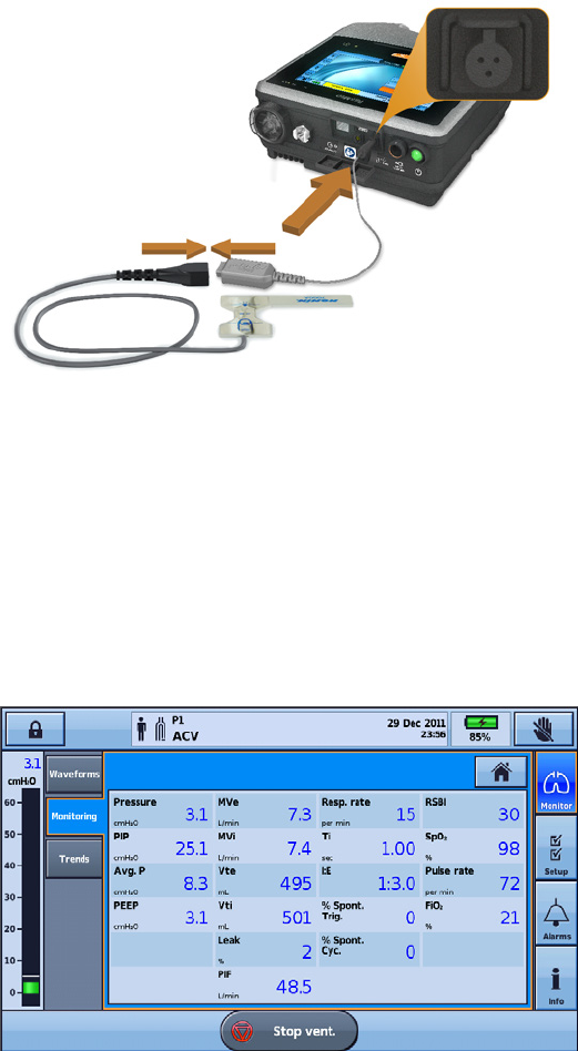
Attaching a pulse oximeter
WARNING
• Only use compatible NONIN™ finger pulse sensors*.
• Pulse oximeter sensors must not be used with excessive pressure for prolonged periods as this
can cause patient pressure injury.
• The pulse oximeter sensor and cable needs to be verified for compatibility with Astral,
otherwise patient injury can result.
CAUTION
Factors that may degrade pulse oximeter performance or affect the accuracy of the measurement
include the following: excessive ambient light, excessive motion, electromagnetic interference,
blood flow restrictors (arterial catheters, blood pressure cuffs, infusing lines, etc.), moisture in the
sensor, improperly applied sensor, incorrect sensor type, poor pulse quality, venous pulsations,
anemia or low hemoglobin concentrations, cardiogreen or other intravascular dyes,
carboxyhemoglobin, methemoglobin, dysfunctional hemoglobin, artificial nails or fingernail
polish, or a sensor not at heart level.
Accessories
English 39
To connect the pulse oximeter:
1. Connect the plug of the finger pulse sensor to the plug of the pulse oximeter.
2. Connect the plug of the pulse oximeter to the SpO
2
(pulse oximeter) connector at the rear of the
device.
*Please refer to the Ventilation accessories on www.resmed.com under the Products page for part
numbers of oximeter accessories with confirmed compatibility. For information on how to use these
accessories, refer to the user guide that comes with these accessories.
Once you have attached the pulse oximeter, a message will briefly display in the information bar.
Real-time SpO
2
and Pulse readings can be viewed from the Monitoring menu.
Notes:
• Values from the SpO
2
sensor are averaged over 4 heartbeats.
• Included SpO
2
sensor is calibrated for the display of functional oxygen saturation.
• The No SpO
2
monitoring alarm will activate if the pulse oximeter has been disabled or has a degraded
signal for more than 10 seconds or has been disconnected.
Accessories
40
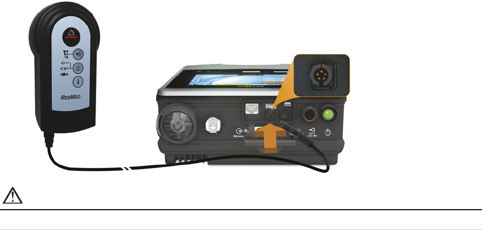
Attaching a remote alarm
The ResMed Remote Alarm II has been designed for use with Astral devices. The Remote Alarm II alerts
you to an alarm that requires immediate attention. It triggers an audible and visual alarm when an alarm
is triggered on the Astral device. For full instructions on using the Remote Alarm II, see the User Guide
that comes with that device.
To connect the Remote Alarm II to the Astral device:
1. Connect one end of the alarm cable to the (3 pin) input connector on the remote alarm.
2. Connect the other end to the (5 pin) output connector located at the rear of the Astral device.
CAUTION
To remove the cable, pull firmly on the connector. Do not twist.

Accessories
English 41
Power management
Helpful hints!
• Connect the ventilator to the mains power whenever possible. In the event of battery failure, connect
to mains power immediately to resume ventilation.
• An external power source (Astral External Battery or RPSII) should always be available for
ventilator-dependent patients.
• An external power source (Astral External Battery or RPSII) should be in use in mobile situations,
including when mains power is unavailable or disrupted. Do not rely solely on the internal battery for
mobile use.
• Ensure the external battery is sufficiently charged before using in mobile situations.
WARNING
• Beware of electrocution. Do not immerse the device, power supply or power cord in water.
• Make sure the power cord and plug are in good condition and the equipment is not damaged.
• Keep the power cord away from hot surfaces.
• Explosion hazard—do not use in the vicinity of flammable anesthetics.
The Astral device can be used with different power sources:
• Mains power
• Astral External Battery
• External DC power supply (eg, car 12V power outlet)
• ResMed Power Station II
• Internal battery
For information on power supplies and sources, refer to the Technical Specifications (see page 72).
Accessories
42
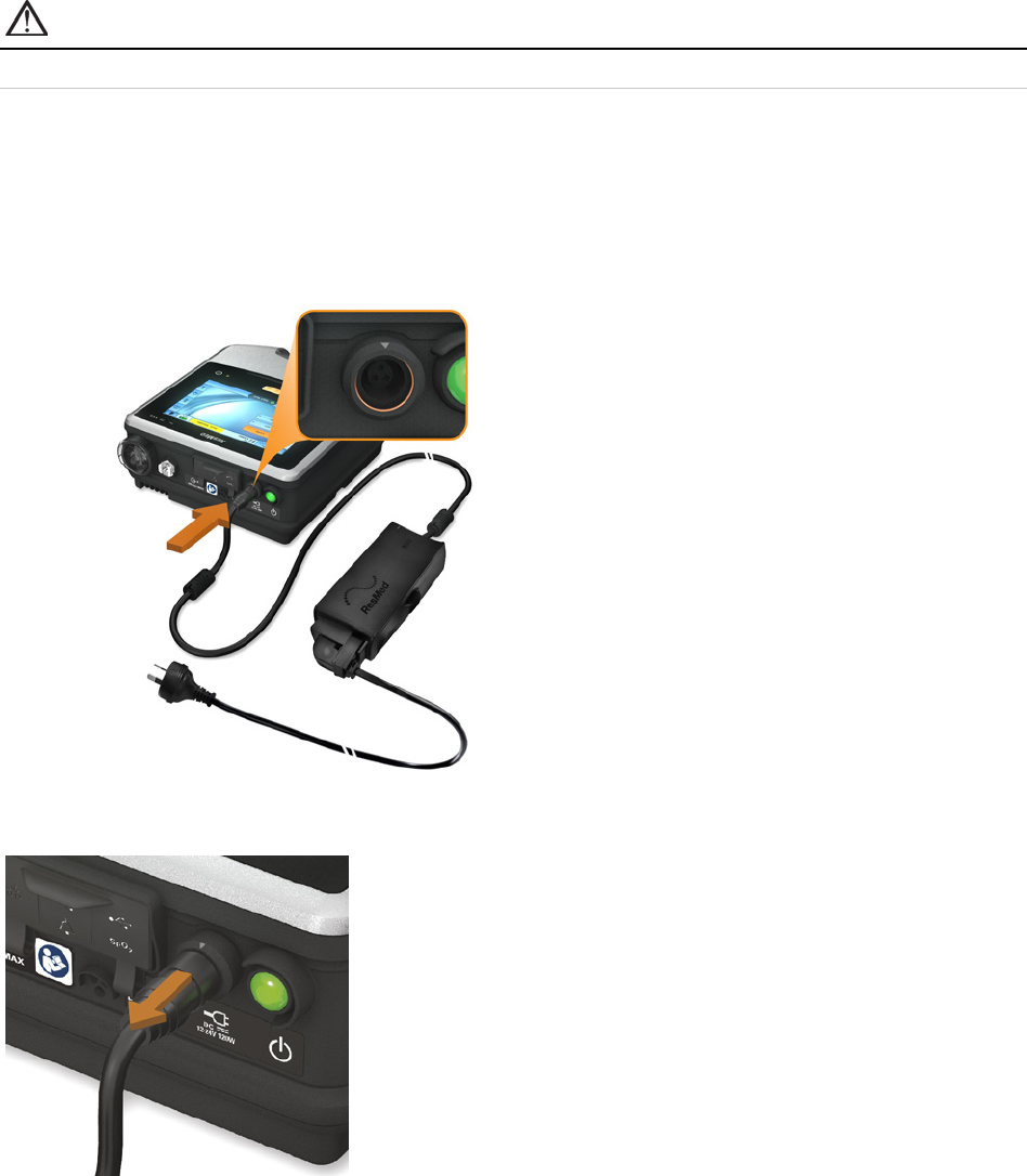
Connecting to mains power
WARNING
Ensure that the power cord does not pose a tripping or choking hazard.
To connect to mains power:
1. Connect the DC plug of the supplied ResMed external power supply unit to the rear of the Astral
device.
2. Before connecting the power cord to the ResMed power supply unit, ensure the end of the
connector of the power cord is correctly aligned with the input socket on the power supply unit.
3. Plug the other end of the power cord into the power outlet.
Note: The power cord is equipped with a push-pull locking connector. To remove, grasp the power cord housing and
gently pull the connector from the device. Do not twist its outer housing or pull on the cord.
Accessories
English 43
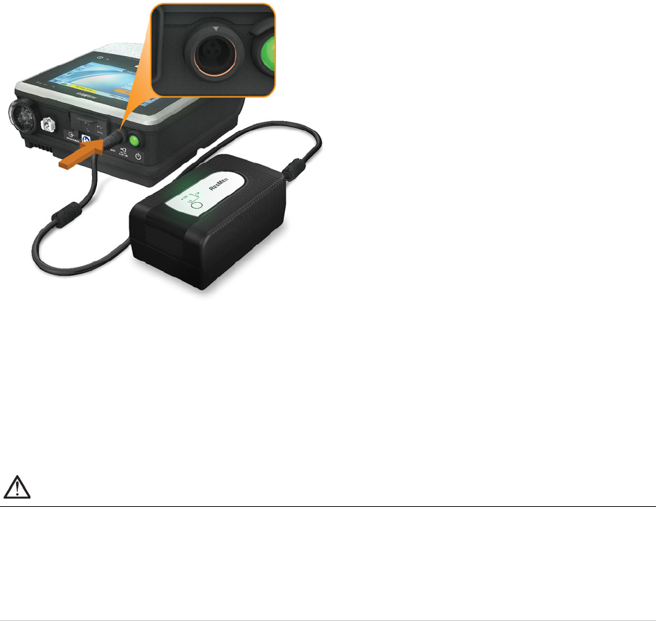
Connecting the Astral External Battery
The Astral External Battery has been designed specifically for use with the Astral Series of ventilators. It
is intended to provide Astral ventilators with eight hours of power during typical use.
For full details on using the Astral External Battery, refer to the External Battery user guide.
Using the External Battery
Connecting a fully charged External Battery to the Astral device can provide 8 hours of power during
typical use. A second fully charged External Battery can be connected to the Astral device to provide a
further 8 hours of power during typical use. A maximum of two external batteries can be connected to
the Astral device.
Once the External Battery is connected to the Astral device, the DC mains indicator on the user interface
will illuminate.
WARNING
•
Do not attempt to connect more than two external batteries. Battery specific messages and
alarms on the Astral device will not operate for any additional units.
• In the unlikely event of an issue occurring with the external battery, Astral will sound an alarm
and notify the user indicating that the device is operating on internal battery power. Ventilation
will continue, however, users should connect to an alternative external power source (eg, AC
power or another external battery) as soon as possible.
Alarms and messages relating to the External Battery may occur from time to time. All message
information will be displayed on the Astral user interface, and will be accompanied by an audible signal.
Refer to the Alarms Troubleshooting (see page 64) for further information.
Accessories
44
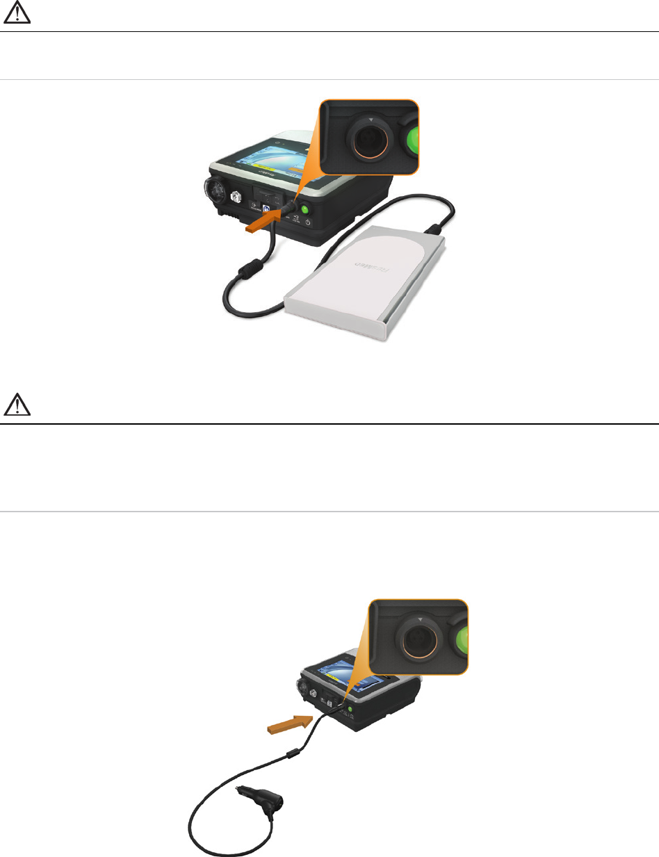
Connecting to a ResMed Power Station (RPSII)
The RPSII provides the Astral device with eight hours of power during typical use. To use, connect the
power cord of the RPSII to the DC inlet port on the device.
CAUTION
•
When using the Astral device with an RPSII, the internal battery will not be charged.
• Do not use the RPSII and external battery together.
Connecting to an external DC power source
CAUTION
• When using a car auxiliary adapter, start the car before plugging in the device's DC adapter.
• If the external DC power source drops to below 11V, the Astral will switch to internal battery.
• When the device is turned off while connected to the DC adapter, it will continue to draw
power from the external DC power source.
To connect DC power:
1. Connect the DC plug of the external DC power supply unit to the rear of the device.
2. Plug the other end of the power cord into the power outlet.

Accessories
English 45
Using the internal battery
An internal battery is included in the Astral device. It ensures a continuous power supply when mains
power is disrupted and no external battery is connected to the device. When the Astral starts using the
internal battery as its power source, you are notified by the Using internal battery alert and with the
internal battery power source indicator.
The internal battery operates for approximately eight hours under typical conditions. During ventilation,
alarms will alert the user to a low battery condition. During standby, no alarms will be announced. The
user should regularly check the battery status.
WARNING
• When using the Astral device as a backup ventilator, ensure the internal battery level is
checked on a regular basis.
• As the battery ages, the available capacity decreases. When the remaining battery capacity is
low, do not rely on the internal battery as the primary power supply.
• The internal battery should be replaced every two years or sooner when there is a noticeable
reduction in usage time when fully charged.
• The internal battery is not intended to serve as a primary power source. It should only be used
when other sources are not available or briefly when necessary; for example, when changing
power sources.
CAUTION
•
Revert to AC mains power when the remaining capacity of the battery is low.
• The internal battery may stop charging when ambient temperatures of 35°C or more are
reached. This will be indicated with a Power fault/No charging alarm message.
• The internal battery will be depleted if the device is left in storage for an extended period of
time. During storage, ensure the internal battery is recharged once every six months.
• Storing the Astral device at temperatures exceeding 50°C for extended periods will accelerate
battery ageing. This will not affect the safety of the battery or the device.
While connected to mains power, the internal battery continues to charge when the device is operating
or in standby.
For more information on the expected operating time of the internal battery, see the Technical
Specifications.
Battery run time
The internal battery powers the Astral device for eight hours under conditions typical to the chronic home
ventilator-dependent patient.
Internal battery run time is determined by the:
• percent charge
• environmental conditions (such as temperature and altitude)
• condition and age of the battery
• device settings
• patient circuit setup and unintentional leak.
The internal battery should be replaced every two years or sooner when there is a noticeable reduction in
usage time when fully charged.
Storing and recharging
If the internal battery is not used, it must be recharged every six months.
Accessories
46
It takes approximately four hours to fully recharge the internal battery from depletion; however this can
vary depending on environmental conditions and the device operating state.
To prepare the internal battery for long-term storage:
1. Check that the battery charge level is between 50 and 100%. If not, charge the device to at least
50% prior to storage.
2. Remove the power cord from the Astral.
3. Turn off the device.
To recharge the internal battery:
1. Connect the device to mains power.
2. Charging commences as indicated by a flashing battery charging indicator symbol in the Information
bar.
Notes:
• When charging a completely depleted battery, it will normally take up to 30 minutes to increase battery capacity
from 0% to 1%.
• If the device has been stored outside the operating temperature range, an alarm message (Power fault / No
charging) may appear. You can still continue using the device, however, if the alarm persists for more than 2
hours the battery may need replacement.
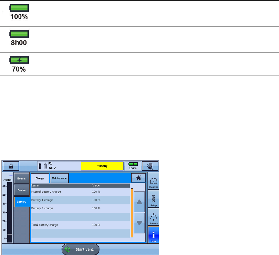
Accessories
English 47
Device power source indicators
Information on system and battery charge levels can be accessed in one of two ways:
1. Battery Indicator
The capacity of all connected batteries will be added to the RunTime indicator on the Information bar
of the Astral interface. (This may take a couple of minutes). The total will be the sum of the Astral
internal battery plus either one or two external batteries.
Under normal operating conditions, the ventilator will display:
- Total system state of charge as a percentage when in ventilation standby mode or connected to
mains power.
- Estimated remaining run time while delivering therapy.
Display Description
When either the external or internal battery is in use, but the device is not ventilating, the battery charge
level is displayed. The battery percentage is an average of all batteries connected to the system. Full
details of individual battery capacities can be reviewed in the Battery information page.
When either the external or internal battery is in use during ventilation, the remaining usage is displayed as
estimated by current operating conditions. The total will be the sum of all batteries connected to the
system.
When either the external or internal battery is charging, the charge battery symbol and percentage charged
is displayed.
Note: Only the Astral external and internal batteries are included in battery indicator calculations. RPSII battery levels are
not displayed.
2. Battery information
The battery information can be accessed from the Battery sub-menu in the Information menu. This
menu has two tabs:
- Charge—displays the current charge level (0-100%) for any batteries currently detected by the
system, as well as the total system charge.
- Maintenance—displays the full charge capacity and the charge cycle count for any batteries
currently detected by the system.
Regularly check the charge level of the internal battery and any connected external batteries. It is
recommended to replace any batteries at 400 charge cycles.
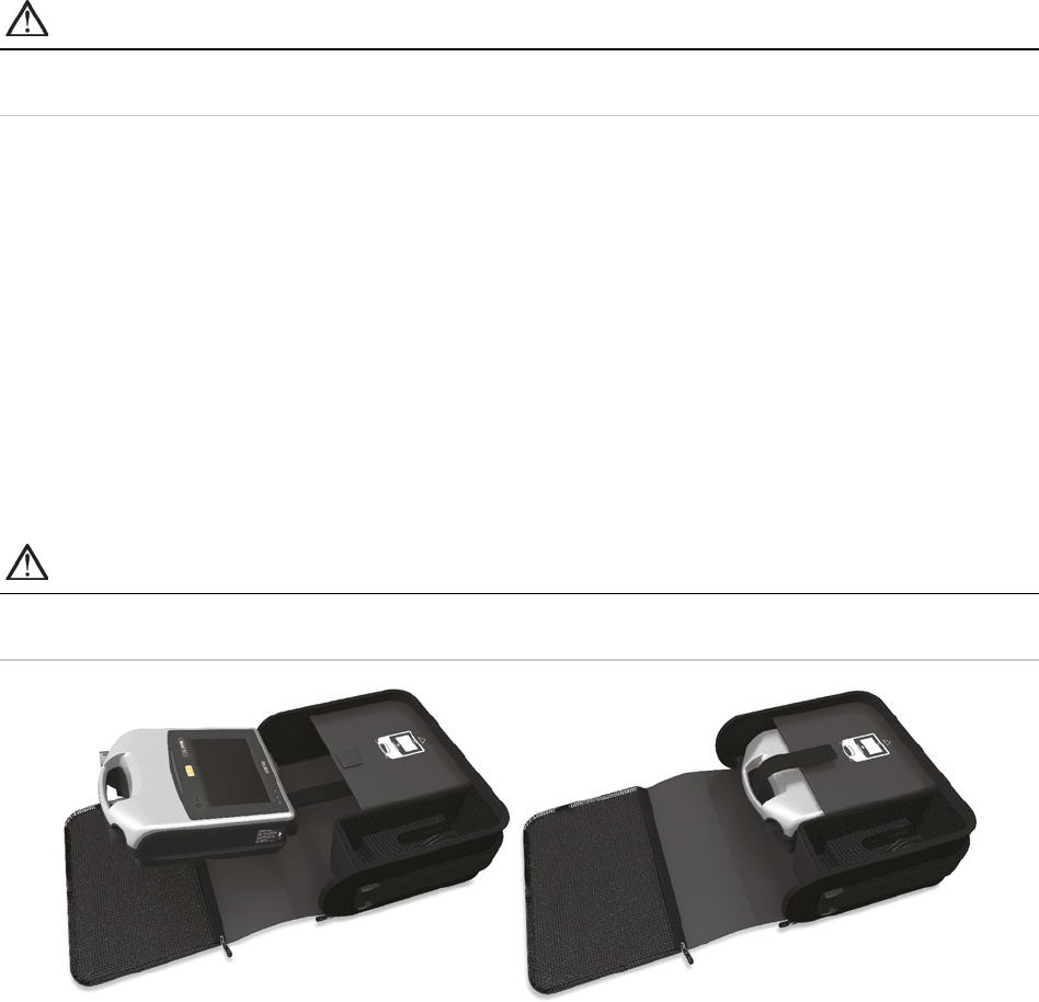
Accessories
48
Astral Carry Bag
The Astral device should always be packed in its Carry Bag when not in use to prevent damage to the
device.
WARNING
The Astral should not be operated while in the Carry Bag. To ventilate while travelling, use the
Astral Mobility bag or SlimFit mobility bag.
To use the Carry Bag
1. Prior to placing the device in the Carry Bag, remove:
- the power connection from the rear of the device
- all patient circuit components
- all accessories, including Remote Alarm and oximeter
- the USB Stick.
2. Place the Astral device carefully into the Carry Bag, ensuring the handle is at the top and the screen
faces the printed image on the bag.
3. Secure the Astral device in place by using the Velcro strap. (To ensure the most secure position,
thread the Velcro strap through the handle and attach.)
4. Place the Power Supply unit and any heavy components in the side zippered pocket.
5. Ensure all zippers are completely closed and the device secure before lifting the Carry Bag.
CAUTION
Do not place any heavy or bulky objects in the zippered pocket on the inside front of the bag. This
could result in damage to the LCD Touch screen.
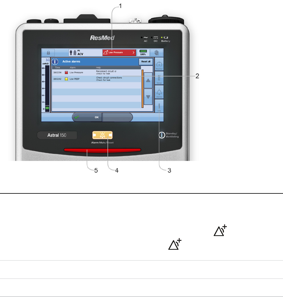
Alarms
English 49
Alarms
The Astral device activates alarms to alert you to conditions that require attention to ensure patient
safety. When an alarm is activated, the Astral device provides both audible and visual alerts, and displays
an alarm message in the Alarm display on the Information bar.
As part of the alarm system (eg, the overpressure protection and system alarms), Astral may perform an
automatic restart. An automatic restart checks systems and ensures correct operation of the alarm.
As soon as the activation condition is met, the Astral device provides both audible and visual alerts
without delay.
Indicator Description
1
Alarm display
Displays either the alarm message for the highest priority active alarm, or the last
alarm not yet reset.
Press the Alarm display for further alarm information.
Certain conditions may result in multiple alarms.
indicates that there are
multiple active alarms. Press
when displayed to view all alarms and
respond appropriately. Alarms are displayed in order of priority.
2
Active Alarms screen
Displays the full set of active alarms. Will automatically display upon activation of
an alarm in Patient mode.
3
Information menu
Some alarms clear automatically. To view a history of alarms, view the alarm log
through the Information menu.

Alarms
50
Indicator Description
4
Alarm mute/reset button State:
• no light – no active alarms
• steady light – active alarm/s
• flashing light – alarm mute on.
This button also allows you to:
• mute the audible alert
• reset the currently displayed alarm (if permitted).
5
Alarm bar Indicates the priority of the alarm in the Alarm display.
Alarm priority
Alarms are classified into relative priority (high, medium and low) according to the severity and urgency
of the alarm condition. Respond to all alarms. An immediate response is required for high priority alarms.
Alarm priority
Alarm bar Audible alert
High
Red flashing light 10 beeps every 5 seconds
Medium
Yellow flashing light 3 beeps every 15 seconds
Low
Yellow steady 2 beeps every 25 seconds
Helpful hint!
For suggestions on resolving most common alarms, refer to Alarms Troubleshooting.

Alarms
English 51
The following list of alarms is ordered by relative importance within priority.
High priority alarms Medium priority alarms Low priority alarms
Total power failure*
High pressure protection
Circuit disconnection
Low Pressure
Obstruction
High Pressure
Apnea
Low MVe
Low MVi
High MVi
High MVe
Low Vte
High Vte
Low Vti
High Vti
Low Resp. rate
High Resp. rate
High leak
Ventilation stopped
Low SpO
2
High SpO
2
Low FiO
2
High FiO
2
NV mask/Rebreathing
Incorrect circuit adapter
Critically low battery
Incorrect circuit attached
Safety reset complete
Battery inoperable
High pressure
Low PEEP
High PEEP
Low pulse rate
High pulse rate
Device overheating
Pressure line disconnected
Last self test failed
Flow sensor not calibrated
No SpO
2
monitoring
No FiO
2
monitoring
Internal battery degraded
Low internal battery
Circuit fault
Using internal battery
Battery 1 fault
Battery 2 fault
Power fault/No charging
PEEP blower failure
*No LED will flash during a Total power failure alarm.
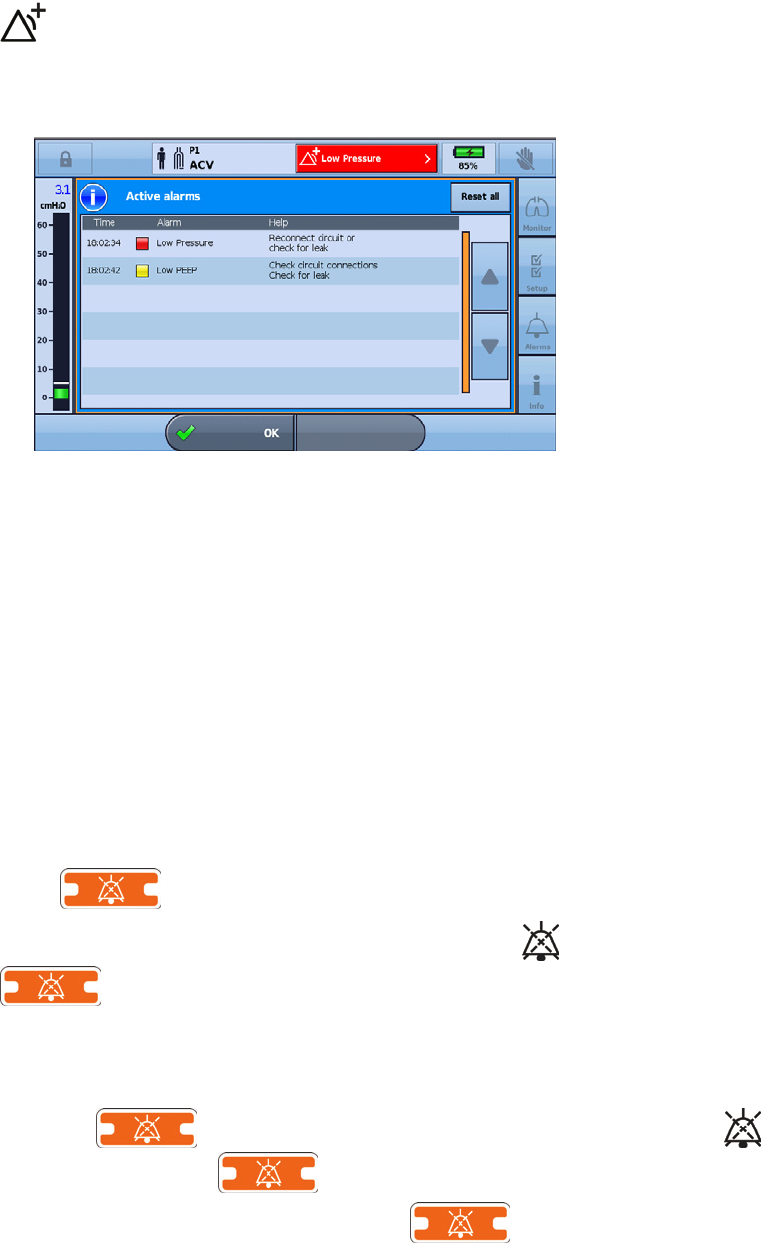
Alarms
52
Viewing the active alarms
in the Alarm display indicates that there are multiple active alarms. Although multiple alarms can be
active simultaneously, the Alarm display only shows the highest priority alarm. The full set of active
alarms is displayed in the Active alarms screen.
When the highest priority alarm is cleared, the next highest priority alarm displays in the Alarm display.
To view the active alarms:
1. From any screen, press the Alarm display on the Information bar. The Active alarms screen is
displayed. This screen contains a full list of currently active alarms, displayed in order of their relative
priority.
2. Press OK to close the Active alarms screen and return to the previous screen.
Muting alarms
You can temporarily mute the audible alert on the Astral device for a two minute period. The Alarm
display and Alarm bar continue to display the alarm as usual. If after two minutes the alarm condition is
still present, the audible alert will sound again.
You can also use the Alarm Mute in advance, to 'pre-silence' alarms that you expect to occur. This can
be helpful during suctioning procedures or when intending to disconnect the patient from the ventilator
for a short period.
To mute the audible alert on an active alarm:
Press
.
The alarm is silenced for two minutes. During that period,
is displayed on the Information bar and
flashes.
Note: Pressing the Alarm mute/reset button again during the Alarm Mute period will reset the displayed alarm. Refer
to Resetting alarms (see page 53).
To silence alarms before they activate:
1. Press
. Alarm mute is active for two minutes. During that period, is displayed on the
Information bar and
flashes.
2. To cancel Alarm mute, press the flashing
again.
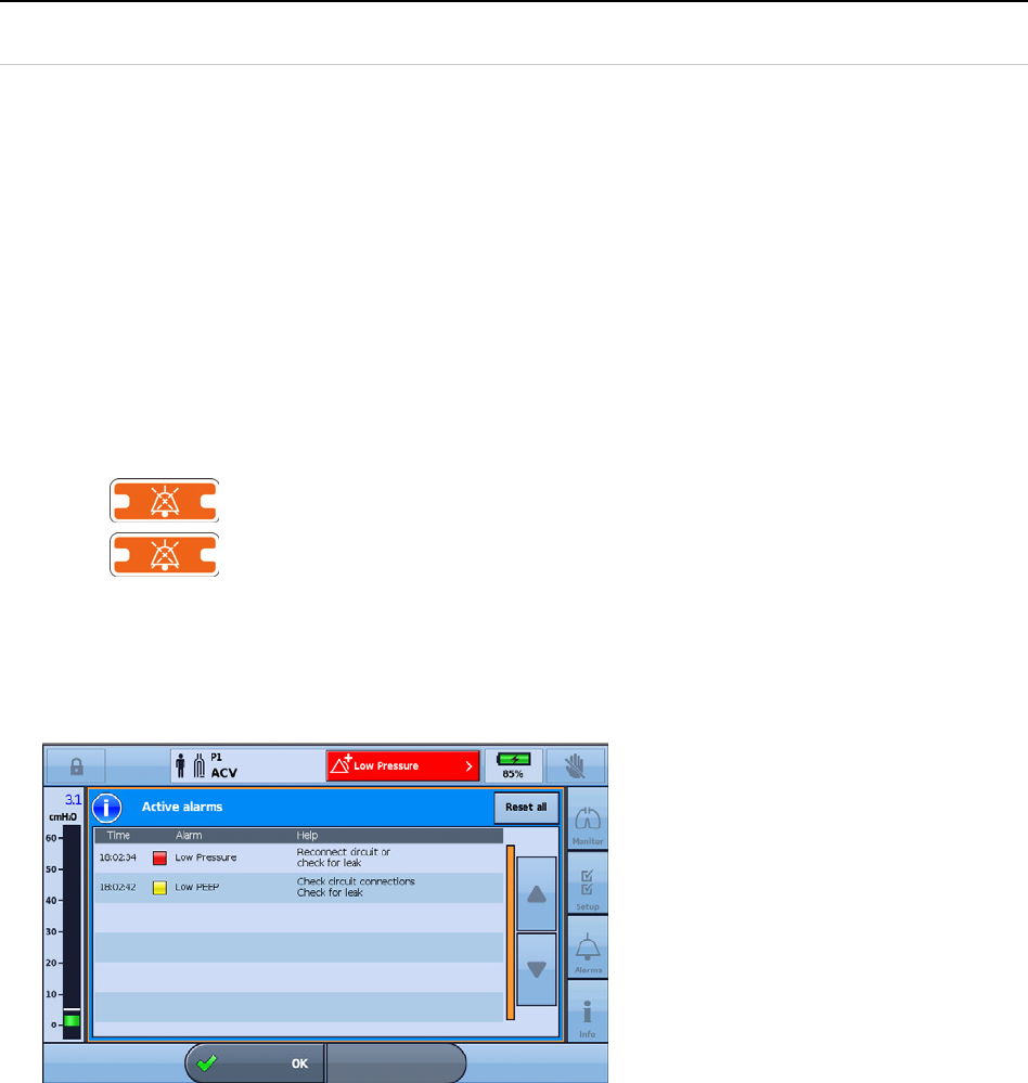
Alarms
English 53
Helpful hint!
You can adjust the volume of the audible alert. For information, refer to Device settings. After any
adjustment, make sure you can still hear the alarm clearly from a distance.
Resetting alarms
Resetting an alarm removes that alarm from the Alarm display and the Active alarms screen, and turns
off the visual and audible alerts. An active alarm should only be reset after the situation that caused the
alarm has been attended to. If the alarm condition has not been corrected, the alarm will activate again.
The Astral device may automatically clear an alarm when the condition that triggered the alarm is
corrected. When an alarm is cleared it no longer displays in the Active alarms screen and the audible and
visual alerts cease.
When an alarm is cleared or manually reset, the Alarm display then shows the next highest priority active
alarm.
Some alarms cannot be manually reset. For these alarms you must correct the cause of the alarm.
Resolving the alarm will automatically clear the display.
To reset the displayed active alarm:
1. Press
to mute the alarm. The button illuminates and flashes.
2. Press
again to reset the alarm. The alarm message is removed from the Alarm display. It
is also cleared from the Active alarms screen.
Note: You can carry out this procedure with the Active alarms screen open, if you want visibility of all the active
alarms as you perform the reset.
To reset all active alarms:
1. Press the Alarm display on the Information bar. The Active alarms screen is displayed.
2. Press Reset all to reset multiple alarms. Only those alarms that can be reset, will be reset. Any
remaining alarms will require user intervention and correction.
3. Complete any required action to resolve the remaining alarms.
4. Press OK to close the Active alarms screen and return to the previous screen.
Adjusting the alarm volume
The volume level of the Astral device can be set from one to five (with five being the loudest and the
default being three). Your Clinician has pre-set a minimum volume level. Any settings below the set
minimum are greyed out and are disabled from use.
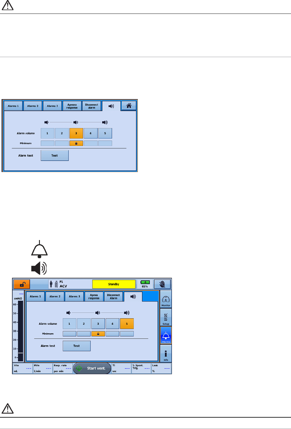
Alarms
54
WARNING
• Alarm volume cannot be adjusted separately for individual alarms. Adjusting the alarm volume
will change the volume of all alarms, independent of alarm priority level.
• When adjusting alarm volume, ensure that the alarm can be heard above the ambient noise
levels that the patient may experience in a variety of settings, including use in noisy
environments or inside mobility bags.
In the example below, your Clinician has maintained the default alarm volume of three. This means the
'1' and '2' volume options are disabled and you are free to increase and decrease the alarm Volume
levels between '3' and '5'. If however, your Clinician had set the minimum volume level at '1', all volume
options would be available for selection.
Testing the alarm sounders and indicators
To confirm the alarm will sound as intended, regularly test the alarm.
The Astral device incorporates two alarm sounders. During an alarm condition both sounders are
operated in parallel. To confirm the correct operation of each sounder, regularly perform the Alarm test
function. During this test each sounder will be operated separately and in sequence.
To test the alarm sounders and indicators:
1. Press
. The Alarms screen is displayed.
2. Press
. The Alarm volume screen is displayed.
3. Press Test to test the alarm. The alarm beeps twice and the LED flashes to indicate it is working
correctly. Confirm the alarm beeps twice. Confirm the Alarm bar flashes red, then yellow. Confirm
the mute button flashes.
WARNING
If no alarm sounds, do not use the ventilator.
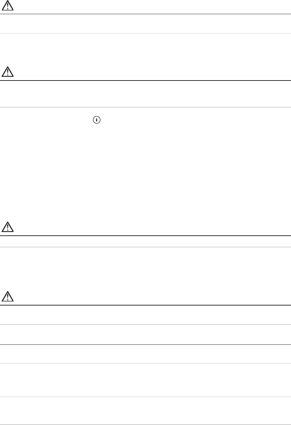
Alarms
English 55
CAUTION
If only one beep is heard, or the Alarm bar does not flash red, then yellow, return the device for
servicing.
Testing the Remote Alarm
The Remote Alarm generates an audible and visual signal when an alarm is triggered on the ventilator.
CAUTION
A test of the Remote Alarm should be performed prior to initial use and every change of battery.
Test the alarm periodically as per the facility policy. For dependent patients perform a test on a
daily basis.
To test the Remote alarm, press
on the Remote Alarm.
The following will occur:
• The alarm LED illuminates and the alarm sounds.
• The LED corresponding to the set volume illuminates.
• The Disconnect LED blinks if the alarm is not connected to the device and lights permanently if
connected.
• The battery level LED corresponding to the battery level illuminates. Yellow LED if battery life is low,
or green LED if battery life is good. (Replace the battery if the battery life is low).
• If a second Remote Alarm is connected, the second Remote Alarm will also sound.
Testing the alarms
WARNING
Do not perform alarm tests while the patient is connected to the ventilator.
This section describes functional tests to allow the user to understand the conditions that can trigger
common Astral alarms. The efficacy of therapy alarm limits should be assessed by your clinician.
Note: In some alarm test procedures multiple alarms will be triggered. To see all of the active alarms, press the
Alarm display button as described in the Viewing the active alarms (see page 52).
CAUTION
When the alarm tests are completed ensure the Astral device is restored to its original state and
the internal battery is charged.
Alarm
Test procedure
Low Pressure
1. Disconnect the patient interface from the circuit.
2. Start ventilation.
Low Vte
(Only possible on Double limb and
Single limb with intentional leak
circuits)
1. Disconnect the patient interface from the circuit.
2. Start ventilation.
Obstruction
1. Disconnect the patient interface from the circuit.
2. Start ventilation.
3. Block the circuit outlet.

Alarms
56
High leak
(Only possible on Double limb and
Single limb with intentional leak
circuits)
1. Disconnect the patient interface from the circuit.
2. Start ventilation.
Low FiO
2
(Only possible to test if the therapy
has been configured for
supplemental oxygen use)
1. Turn off the supplemental oxygen.
2. Start ventilation.
High FiO
2
(Only possible to test if the therapy
has been configured for
supplemental oxygen use)
1. Adjust supplemental oxygen to a higher flow rate.
2. Start ventilation.
Using internal battery
1. Ensure the Astral device is connected to an external power source.
2. Power on the Astral device.
3. Disconnect the power cord.
Low battery
Critically low internal battery
1. Ensure the Astral device is powered on and is operating on the internal battery.
2. Go to the Setup menu and select Device Config. Turn off the Auto power off and
Backlight timeout settings. Refer to Adjusting device settings (see page 19).
3. Wait for the internal battery to run flat. This will take over 10 hours from a fully
charged internal battery.
Power alarms
CAUTION
Data cannot be saved while there is a Critically low battery or Battery inoperable alarm. Program
selections made while these alarms are active may be lost if the device is restarted. Recording of
ventilation data and alarms is suspended.
Alarm Activates when
Low internal battery
Approximately 20 minutes of ventilation time remaining on internal battery power.
Critically low battery
Approximately 10 minutes of ventilation time remaining on internal battery power.
Total power failure
There is total loss of power due to failure of the internal battery, or a loss of external power while
the internal battery is removed or fully depleted/discharged.
Power disconnected
The power source is changed from an external source to the internal battery.
Using internal battery
The Astral device is powered on and is using battery power.
Battery inoperable
The internal battery is faulty or has been removed.
Internal battery
degraded
The internal battery is degraded and may not provide a reliable indication of remaining time.

Detecting circuit disconnection and de-cannulation
English 57
Detecting circuit disconnection and de-cannulation
Inadvertent disconnection of a circuit component or accidental removal of a cannula poses a hazard to a
dependent patient. Astral is equipped with a number of alarms that when used in conjunction with the
Disconnection Alarm are able to reliably detect circuit disconnection (including de-cannulation).
The optimal alarm may depend on the therapy target and circuit type as shown in the table below.
However, Astral provides a number of alarms that can be configured by your clinician specifically for this
purpose.
WARNING
Alarm settings are sensitive to any changes to the circuit, ventilation settings or co-therapy. Test
the effectiveness of the alarm after any of these changes are made.
CAUTION
Alarms should be configured and tested to ensure that circuit disconnection and de-cannulation is
detected. We recommend configuring and testing multiple alarms and testing disconnection at the
ventilator and at the cannula. Independent monitoring can be used as an alternative.
The following table provides the most appropriate alarms for use in detecting circuit disconnection.
Pressure target modes Volume target modes
Single with leak
Disconnection alarm
Low pressure alarm
Low Vte alarm
Low MVe alarm
Apnea alarm
Leak alarm
SpO
2
alarm
N/A
Single with valve
Disconnection alarm
Low pressure alarm
Low Peep alarm
High Vti alarm
High MVi alarm
Apnea alarm
SpO
2
alarm
Disconnection alarm
Low pressure alarm
Low PEEP alarm
Apnea alarm
SpO
2
alarm
Double with valve
Disconnection alarm
Low pressure alarm
Low Vte alarm
Low MVe alarm
Apnea alarm
Leak alarm
SpO
2
alarm
Mouthpiece
Disconnection alarm
Low pressure alarm
High Vti alarm
High MVi alarm
Apnea alarm
SpO
2
alarm
Disconnection alarm
Low pressure alarm
Apnea alarm
SpO
2
alarm
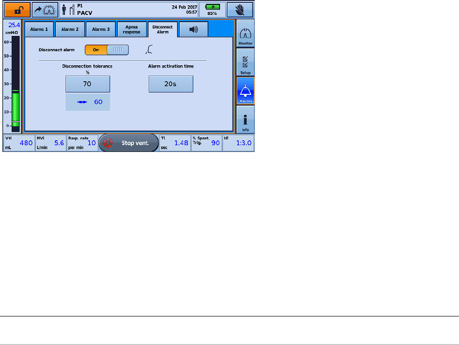
Detecting circuit disconnection and de-cannulation
58
Astral Disconnection Alarm
The Astral Disconnection Alarm constantly measures circuit resistance to detect disconnection during
therapy. The high priority Disconnection Alarm will activate when the device detects a disconnection that
persists continuously for more than the alarm Activation Time preset by your clinician. If the degree of
disconnection is resolved within this time, the Alarm Activation Time will be reset.
Adjusting the Disconnection Alarm
Your clinician can adjust the Disconnection Alarm to suit your needs. Your clinician can:
1. Adjust alarm Activation Time – the time it takes (in seconds) following disconnection for the alarm to
activate
2. Adjust Disconnection Tolerance – the degree of disconnection that it takes to activate the alarm
3. Turn the Disconnection Alarm On/ Off.
Note: The Disconnection Alarm default setting is On.
To test the Disconnection Alarm:
These steps should be performed prior to connecting patient to the ventilator.
1. Attach all components of the patient circuit, including interface (a test cannula should be used in the
case of a tracheostomy).
2. Start ventilation at the appropriate therapy settings, circuit configuration, and supplemental oxygen (if
required).
3. Check that the measured disconnection value turns red and that the Disconnection Alarm activates
after the Alarm Activation Time.
Note: If the Disconnection Alarm does not sound, the alarm parameters may need to be adjusted by your clinician.
Helpful hint!
De-cannulation can be the most difficult disconnection for the device to detect. To ensure de-cannulation
is detected, test the Disconnection Alarm using a test cannula. Your clinician can help you to do this.
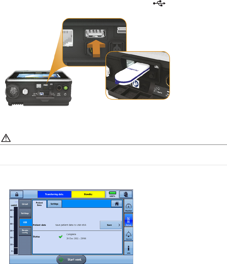
Data management process
English 59
Data management process
Monitoring data from the Astral device can be viewed in the ResScan™ patient management software.
Data is transferred from the device to ResScan using a USB stick. Once downloaded to ResScan, the
data can be viewed in several report formats to easily monitor treatment results and compliance.
To connect the ResMed USB to the Astral device:
Plug a USB stick into the USB connector at the rear of the device. The
symbol is displayed in the
Information bar to indicate the USB is attached.
To remove the USB stick, simply pull it out of the USB connector on completion of transfer. If data was
being transferred at the time, a message in the Information bar alerts you to a failed transfer.
WARNING
Only connect devices specially designed and recommended by ResMed to the data
communication ports. Connecting other devices could result in patient injury, or damage to the
Astral device.
To transfer data:
1. From the Settings menu select Patient Data from the USB sub-menu.
2. Press Save >. When the transfer is complete a status message is displayed.
3. Press Clear to acknowledge you have read the message and enable further transfers.
4. Remove the USB stick from the Astral device.
5. At the computer where ResScan is installed, plug the USB stick into the USB port.
6. Follow the download procedure specified in the ResScan User Guide.

Cleaning and maintenance
60
Cleaning and maintenance
The cleaning and maintenance described in this section should be carried out regularly.
Refer to the user guides for the patient interface, humidifier and other accessories in use for detailed
instructions for care and maintenance of those devices.
WARNING
• A patient treated by mechanical ventilation is highly vulnerable to the risks of infection. Dirty or
contaminated equipment is a potential source of infection. Clean the Astral device and its
accessories regularly.
• Always turn off and unplug the device before cleaning and be sure it is dry before plugging
back in.
• Do not immerse the device, pulse oximeter or power cord in water.
CAUTION
Clean only exterior surfaces of the Astral device.
When required, wipe the exterior of the device with a damp cloth using an approved mild cleaning
solution.
For all circuit components, follow the manufacturer's recommendations for cleaning and maintenance.
Weekly
1. Inspect the condition of the circuit adapter for entry of moisture or contaminants. Replace as
necessary.
2. Test the alarm sounders, refer to Testing the alarm sounders (see page 54).
Helpful hint!
For information on removing and replacing the circuit adapter, refer to Fitting the circuit adapter (see
page 23).
Monthly
1. Inspect the condition of the air filter and check whether it is blocked by dirt or dust. With normal use,
the air filter needs to be replaced every six months (or more often in a dusty environment).
2. Check the charge level of the internal battery by:
- removing external power and operating the device on internal battery for a minimum of 10
minutes.
- reviewing the remaining battery capacity, refer Using the Internal battery (see page 45).
- restoring external power once the test is complete.
To remove and replace the air filter
1. Unlock the air filter cover by turning in an anti-clockwise direction.
2. Pull the air filter cover from the device.
3. Pull the air filter from the cover and discard.
4. Insert a new filter into the cover.
5. Insert the air filter and cover back into the device.
6. Turn in a clockwise direction to secure in place.
Cleaning and maintenance
English 61
Servicing
WARNING
Inspection and repair should only be performed by an authorised agent. Under no circumstances
should you attempt to service or repair the device yourself. Failure to do so could void your Astral
device warranty, damage the Astral device or result in possible injury or death.
Note: Retain the original packaging of the Astral device for use when shipping to/from an authorised ResMed Service
Centre.
WARNING
• To prevent the risk of cross-contamination, an antibacterial filter, placed on the inspiratory port
is mandatory if the device is to be used on multiple patients as under some fault conditions,
expired gas may be returned through the inspiratory port.
• The expiratory module, internal antibacterial filter, expiratory flow sensor and blue membrane
come into contact with exhaled gases but do not form part of the inspiratory pathway.
Replacing the air filter
Inspect the condition of the air filter and check whether it is blocked by dirt or dust. With normal use, the
air filter needs to be replaced every six months (or more often in a dusty environment).
CAUTION
Do not wash the air filter. The air filter is not washable or reusable.
To remove and replace the air filter
Before replacing the air filter, turn off the device and remove mains power and/or external battery.
1. Unlock the air filter cover by turning in an anti-clockwise direction.
2. Pull the air filter cover from the device.
3. Pull the air filter from the cover and discard.
4. Insert a new filter into the cover.
5. Insert the air filter and cover back into the device.
6. Turn in a clockwise direction to secure in place.

Cleaning and maintenance
62
Maintenance Timetable
The Astral device should be serviced by an authorised ResMed Service Centre according to the following
schedule. The Astral device is intended to provide safe and reliable operation provided that it is operated
and maintained in accordance with the instructions provided by ResMed. As with all electrical devices, if
any irregularity becomes apparent, you should exercise caution and have the device inspected by an
authorized ResMed Service Centre.
With regular servicing, the expected service life of an Astral device is 8 years.
Servicing schedule from the date of first use:
Recommended service interval Conducted by Instructions
Every six months
Personnel who have been trained in the
use of Astral
Replacement of the air filter (replace
earlier if dirty).
Replacement of Single or Double limb
circuit adapters if used.
Two years Qualified technician
Two year Preventative maintenance.
Replacement of the internal battery and
FiO
2
sensor if fitted.
35,000 hours Qualified technician
Pneumatic block Preventative
maintenance.
Helpful hint!
If Service Reminders are enabled you will get a notification on the device when two year preventative
maintenance is nearly due.
Internal Battery
The expected life of the internal battery is two years. The internal battery should be replaced every two
years or sooner when there is a noticeable reduction in usage time when fully charged. During storage
ensure that internal battery is recharged once every six months.
Helpful hint!
If Service reminders are enabled you will get a notification on the device when there is a measurable
reduction in battery usage time.
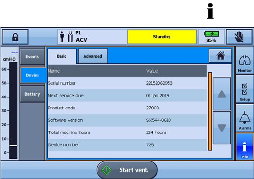
Cleaning and maintenance
English 63
Device information
Device information, including the Next service due date indicating when the next preventative
maintenance is due, can be found by pressing
and selecting Device.

Troubleshooting
64
Troubleshooting
If there is a problem, try the following suggestions. If the problem cannot be solved, contact your care
provider or ResMed.
Alarm troubleshooting
The most common reason for an alarm to sound is because the system has not been properly
assembled or a Learn Circuit has not been correctly performed for each program.
Notes:
• The alarm actions listed below are based on having the appropriate alarm settings for the patient's therapy.
When an adjustable alarm is activated, re-confirm the alarm settings.
• The alarm log and alarm settings are maintained when the device is powered down and in the event of a power
loss.
• If an alarm activates repeatedly, discontinue use, switch to a backup ventilator and return the device for
servicing.
If the alarm log reaches its storage capacity, the oldest data will be discarded to allow new entries to be
written to the log.
Alarm message Action
Apnea
1. Check the patient's status and airway.
2. Inspect the circuit and proximal lines for leak. Perform a Learn Circuit.
Battery 1 fault
Check battery connections. If problem persists replace External Battery 1 with new
external battery.
Battery 2 fault
Check battery connections. If problem persists, replace External Battery 2 with a new
external battery.
Battery Inoperable
1. If the device has been stored in extreme temperatures, wait until the device returns
to room temperature.
2. If the device has been stored for long periods of time, the battery may have
discharged. Connect to mains power.
3. If alarm persists, return the device for servicing.
Circuit fault
1. Check the circuit for water or leaks.
2. Perform a Learn Circuit.
3. If the alarm persists, replace the circuit.
Critically low battery Connect the Astral to mains AC power and allow the battery to recharge.
Device overheating
1. Move the device to a cooler location.
2. Inspect the air inlet for foreign objects.
3. Inspect the air inlet filter. If necessary, replace the air inlet filter.
4. Inspect the cooling fan inlet and outlet for foreign objects.
5. Remove the Astral from the mobility bag.
6. Check the circuit for obstructions.
7. Perform a Learn Circuit.
Disconnection alarm
1. Check the patient's status and airway.
2. Inspect the circuit and proximal lines for disconnection or excessive leak.
3. Perform a Learn Circuit.
Flow sensor fault Replace expiratory flow sensor.
Flow sensor not calibrated Perform a Learn Circuit.

Troubleshooting
English 65
Alarm message Action
High FiO
2
1. Check the patient's status.
2. Check and adjust the oxygen supply.
3. Perform a Learn Circuit to recalibrate the oxygen sensor.
High Leak
1. Check the patient's status.
2. Inspect the circuit, expiratory valve and proximal lines for leak. When in use, check
for leaks around the mask.
3. When using vented therapy, check the mask type setting.
4. Perform a Learn Circuit.
High MVe
1. Check the patient's status.
2. Inspect the expiratory valve. If necessary, replace the expiratory valve.
3. Perform a Learn Circuit.
High MVi
1. Check the patient's status.
2. Inspect the circuit and expiratory module for leaks.
3. Perform a Learn Circuit.
High PEEP
1. Check the patient's status.
2. Inspect the circuit and expiratory valve for obstruction. When in use, check for
obstruction in proximal lines.
3. Perform a Learn Circuit.
High pressure
1. Check the patient's status and airway.
2. Inspect the circuit for obstruction.
3. Perform a Learn Circuit.
High pressure protection
The hardware pressure safety limit was exceeded. If problem reoccurs, return the device
for service.
High Pulse Rate Check the patient's status.
High Resp Rate
1. Check the patient's status.
2. Perform a Learn Circuit.
High SpO
2
Check the patient's status.
High Vte
1. Check the patient's status.
2. Inspect the expiratory valve. If necessary, replace the expiratory valve.
3. Perform a Learn Circuit.
High Vti
1. Check the patient's status.
2. Inspect the circuit and expiratory module for leaks.
3. Perform a Learn Circuit.
Incorrect circuit adapter
1. Check that the correct circuit adapter is installed for the selected circuit type.
2. Perform a Learn Circuit.
Incorrect circuit attached
1. Check that the circuit is correctly connected and matches the circuit type selected.
2. Inspect the circuit, expiratory valve and proximal lines.
3. Perform a Learn Circuit.
Internal battery degraded
1. Connect the Astral to mains AC power.
2. Return the device for service to replace the internal battery.
The internal battery run time indicator may no longer be accurate and should not be relied
upon.
Last self-test failed
1. Perform a Learn Circuit.
2. If problem persists, return the device for service.

Troubleshooting
66
Alarm message Action
Low internal battery Connect the Astral to mains AC power to allow the battery to recharge.
Low FiO
2
1. Check the patient's status.
2. Check for leak.
3. Check the oxygen supply and connections to the device.
4. Perform a Learn Circuit to recalibrate the oxygen sensor.
Low MVe
1. Check the patient's status and airway.
2. Inspect the circuit and the expiratory valve for obstruction or leaks.
3. Perform a Learn Circuit.
Low MVi
1. Check the patient's status and airway.
2. Inspect the circuit for obstruction.
3. Perform a Learn Circuit.
Low PEEP
1. Check the patient's status.
2. Inspect the circuit and the expiratory valve for obstruction or leaks. When in use,
check for obstructions in proximal lines.
3. Perform Learn Circuit.
Low pressure
1. Check all circuit connections, especially the patient interface and the proximal sense
line.
2. Inspect the circuit and expiratory valve for damage or secretions.
3. Perform a Learn Circuit.
Low Pulse Rate Check the patient's status.
Low SpO
2
Check the patient's status.
Low Vte
1. Check the patient's status and airway.
2. Inspect the circuit and the expiratory valve for obstruction or leaks.
3. Perform a Learn Circuit.
Low Vti
1. Check the patient's status and airway.
2. Inspect the circuit for obstruction.
3. Perform a Learn Circuit.
No FiO
2
monitoring Perform a Learn Circuit to calibrate the oxygen sensor.
No SpO
2
monitoring
1. Check the SpO
2
connection to patient's finger and the Astral.
2. If the alarm persists, use another SpO
2
oximeter or finger sensor.
NV Mask/Rebreathing For vented circuit:
1. Check that the mask vents are clear and unobstructed.
2. Check the mask type setting.
3. Perform a Learn Circuit.
For mouthpiece circuit:
Check that the interface is a mouthpiece and that the patient is not continuously exhaling
into the circuit.
Obstruction
1. Check the patient's status and airway.
2. Inspect the circuit and the expiratory valve for obstruction. When in use, check for
kinks in proximal lines.
3. Check the circuit for water.
4. Perform a Learn Circuit.
PEEP blower failure
1. Check the patient's status.
2. Switch to a back-up ventilator and return the device for service.

Troubleshooting
English 67
Alarm message Action
Pressure Line disconnected
1. Check the connection of the proximal sense line.
2. Check the circuit for water.
3. Perform a Learn Circuit.
Power fault / no charging
1. Check all connections between the device and external battery.
2. Check connection to mains power (if present). This can be caused by the battery
temperature being out of range.
If problem persists, contact your ResMed Service Centre.
Safety reset complete The device detected a fault and was reset.
1. Check the patient's status.
2. If the alarm persists, switch to a back-up ventilator and return the device for service.
Safety system fault
1. Check the patient's status.
2. Transfer the patient to an alternate means of ventilation.
3. Return the device for servicing.
System fault
1. Check the patient's status.
2. Perform a Learn circuit.
3. If problem persists, or the device fails self-test, return the device for service.
Total power failure
1. Check the patient's status and airway.
2. Connect the device to AC mains.
3. Check the battery charge level of the internal and external (if applicable) battery.
The total power failure alarm can only be silenced by connecting the device to
AC mains power.
Using internal battery Confirm operation on internal battery is intended or restore external power.
If intending to use external power:
1. Check the power cable connection between the mains or battery, the power supply
pack and the device.
2. If using an external battery, check the external battery charge level and
replace/charge if empty.
3. If using mains AC, check the supply output.
4. If the problem continues, try an alternative external supply type (ie, Mains AC, Mains
DC or External Battery).
Ventilation stopped Confirm it is appropriate to stop ventilation.

Troubleshooting
68
Learn Circuit troubleshooting
Error code Action
001 Hardware fault detected. Contact an authorised Service Centre.
104, 105
During the first step of the Learn Circuit, check that the inspiratory port and air inlet filter
of the Astral device are clear of obstructions; and the circuit is not connected to the
inspiratory port.
Repeat Learn Circuit. If the problem persists, contact an authorised Service Centre.
106 Hardware fault detected. Contact an authorised Service Centre.
113
1. Check that supplemental oxygen is not added during the Learn Circuit.
2. During the first step of the Learn Circuit, check that the inspiratory port and air inlet
filter of the Astral device are clear of obstructions; and the circuit is not connected to
the inspiratory port.
Repeat Learn Circuit. If the problem persists, contact an authorised Service Centre.
121 Device Test cannot detect the correct circuit adapter.
Single limb with expiratory valve:
1. Check that the valve control line and proximal pressure line are connected to the
single limb adapter correctly. Refer to Connecting a single limb circuit with expiratory
valve for further information.
2. Check that the single limb circuit adapter is firmly inserted and adapter cover is
installed correctly. Refer to Fitting the circuit adapter (see page 23) for further
information.
Double limb:
1. Check that the double limb circuit adapter is firmly inserted and adapter cover is
installed correctly. Refer to Fitting the circuit adapter (see page 23) for further
information.
Single limb with intentional leak:
1. Check the single limb leak adapter is firmly inserted and adapter cover is installed
correctly. Refer to Fitting the circuit adapter (see page 23) for further information.
Repeat Learn Circuit. If the problem persists, contact an authorised Service Centre.
122 Hardware fault detected. Contact an authorised Service Centre.
123 Air Inlet Filter is not detected.
Check that the air inlet filter is clean, dry and correctly installed. Replace if necessary.
Refer to Replacing the air filter.
Repeat Learn Circuit. If the problem persists, contact an authorised Service Centre.
124
Ensure that all filters and circuits are disconnected from the inspiratory port. Repeat Learn
Circuit. If the problem persists, contact an authorised Service Centre.
125 Hardware fault detected. Contact an authorised Service Centre.

Troubleshooting
English 69
Error code Action
204 Unable to learn the circuit.
1. Ensure that the circuit is not moved until completion of the test.
2. Check the circuit and attached accessories for blockages.
3. Ensure that there are no sharp bends or kinks in the circuit and the patient end is not
blocked.
4. If using humidification, ensure that the humidifier tub is not overfilled.
5. Follow the on-screen instructions carefully:
• circuit should not be blocked during step 2
• circuit should be completely blocked during step 3.
If the problem persists, contact your clinician or an authorised Service Centre.
205 The measured circuit resistance exceeds safe operating limits for this device.
1. Check the circuit and attached accessories for blockages.
2. Ensure that there are no sharp bends or kinks in the circuit and the patient end is not
blocked.
3. If using humidification, ensure that the humidifier tub is not overfilled.
4. Follow the on-screen instructions carefully:
• circuit should not be blocked during step 2
• circuit should be completely blocked during step 3.
If the problem persists, contact your clinician or an authorised Service Centre.
206 Hardware fault detected. Contact an authorised Service Centre.
303 Unable to calibrate oxygen sensor.
1. Check that supplemental oxygen is not added during the Learn Circuit.
2. Repeat Learn Circuit.
If the problem persists, contact an authorised Service Centre.
404, 405, 406 Hardware fault detected. Contact an authorised Service Centre.
409 Learn Circuit was unable to complete due to excessive leak from the circuit.
1. Check that the circuit is completely blocked duri
ng the third step of the Learn Circuit.
2. Check that the circuit is assembled correctly and there are no leaks in the circuit.
3. Check that the circuit adapter is firmly inserted.
4. This circuit may not be compatible with the Astral device. Try another circuit.
Repeat Learn Circuit. If the problem persists, contact an authorised Service Centre.
415 Hardware fault detected. Contact an authorised Service Centre.
420 The measured circuit compliance exceeds safe operating limits for this device.
Check that the circuit is assembled correctly and completely blocked during the third step
of the Learn Circuit.
If the problem persists, contact your clinician or an authorised Service Centre.
426 Hardware fault detected. Contact an authorised Service Centre.

Troubleshooting
70
Error code Action
504 Unable to learn the circuit.
1. Ensure that the circuit is not moved until completion of the test.
2. Check the circuit and attached accessories for blockages.
3. Ensure that there are no sharp bends or kinks in the circuit and the patient end is not
blocked.
4. If using humidification, ensure that the humidifier tub is not overfilled.
5. Follow the on-screen instructions carefully:
• circuit should not be blocked during step 2
• circuit should be completely blocked during step 3.
If the problem persists, contact your clinician or an authorised Service Centre.
505 The measured circuit resistance exceeds safe operating limits for this device.
1. Check the circuit and attached accessories for blockages.
2. Ensure that there are no sharp bends or kinks in the circuit and the patient end is not
blocked.
3. If using humidification, ensure that the humidifier tub is not overfilled.
4. Follow the on-screen instructions carefully:
• circuit should not be blocked during step 2
• circuit should be completely blocked during step 3.
If the problem persists, contact your clinician or an authorised Service Centre.
506, 512 Hardware fault detected. Contact an authorised Service Centre.
600 Unable to calibrate Expiratory Flow Sensor.
1. Check the circuit adapter is clean, dry and firmly inserted.
• If the adapter is wet, then removing the adapter and vigorously shaking to clear
water can be effective. Re-insert adapter firmly and repeat Learn Circuit.
• If the adapter is not clean, then it will need to be replaced.
2. If using a small diameter pediatric breathing circuit, consider using an anti-bacterial
filter or a 22-mm adapter on the expiratory adapter port.
3. Repeat Learn Circuit and ensure that the circuit is not moved until completion of the
test.
If the problem persists, contact an authorised Service Centre.

Troubleshooting
English 71
General troubleshooting
Issue Action
Condensation forming in circuit
Condensation may form due to high humidity settings and low ambient temperatures.
Adjust humidifier settings in accordance with manufacturer's instructions.
Touch screen damaged or
non-responsive
If you are unable to power off the Astral device normally, use the following forced
shutdown procedure:
1. Disconnect any external power source (eg, AC mains or external battery).
2. Press and hold the green on/off button and the alarm mute/reset button for at least
10 seconds. After 10 seconds the alarm bar will flash yellow.
3. Release both buttons. Astral will then power off.
4. The Astral device can be powered back on by pressing the on/off button and used as
intended.
Unable to save data from Astral to
USB or USB is not detected by
device.
1. Remove and reinsert the USB stick.
2. Use a new USB stick.
3. Remove the AC or external DC power supply, the restart the Astral by switching it off
then on.
4. Reformat your USB stick. Note that any data currently saved on the USB will be lost.
Learn Circuit failed
If the Learn Circuit fails and a warning message appears on the top of the Learn Circuit
results page, try the following:
1. Check the circuit for Leak.
2. Check the module, the blue membrane and sensor are pressed all the way in and sit
flush with the enclosure.
3. Hold the circuit straight to reduce resistance.
Note: It is acceptable to use a circuit that gives a caution message as the Astral device
will compensate for circuit resistance and compliance.
Flow Sensor failed
(Astral 150 only)
If the Flow Sensor fails and a message appears on the bottom of the Learn Circuit results
page, try the following:
1. Check the circuit for Leak.
2. Check the expiratory valve, the blue membrane and sensor are pressed all the way in
and sit flush with the enclosure.

Technical specifications
72
Technical specifications
Operating pressure range
Single limb with valve or double limb with valve: 3 to 50 hPa
Single limb with intentional leak: 2 to 50 hPa
CPAP: 3 to 20 hPa
Maximum working pressure limit: 10 to 80* hPa
*Not applicable on all device variants
Forced cycling occurs if the Pressure alarm limit is exceeded.
Operating tidal volume range
(volume control modes)
Adult patient type: 100 to 2500 mL
Pediatric patient type: 50 to 300 mL*
Circuit resistance and compliance
range for stated accuracy of
monitoring and control**
Pediatric patient setting:
Circuit resistance range (circuit with intentional leak): 0 to 8 hPa at 60 L/min
Circuit resistance range (circuit with valve): 0 to 20 hPa at 60 L/min
Circuit resistance range (mouthpiece circuit): 0 to 5 hPa at 60 L/min
Circuit compliance range: 0 to 4 mL / hPa
Adult patient setting:
Circuit resistance range (circuit with intentional leak): 0 to 20 hPa at 120 L/min
Circuit resistance range (circuit with valve): 0 to 35 hPa at 120 L/min
Circuit resistance range (mouthpiece circuit): 0 to 15 hPa at 120 L/min
Circuit compliance range: 0 to 4 mL / hPa
Breathing resistance under single
fault***
Pediatric circuit
Inspiration: 2.2 hPa (at 15 L/min), 5.3 hPa (at 30 L/min)
Expiration: 2.4 hPa (at 15 L/min), 5.0 hPa (at 30 L/min)
Adult circuit
Inspiration: 5.7 hPa (at 30 L/min), 8.3 hPa (at 60 L/min)
Expiration: 4.2 hPa (at 30 L/min), 6.2 hPa (at 60 L/min)
Maximum flow
220 L/min
Inspiratory trigger (nominal)
characteristics
Inspiratory trigger occurs when patient flow exceeds trigger setting.
Double limb with valve (flow trigger): 0.5 to 15.0 L/min
Single limb with valve or double limb with valve: 1.6 to 10.0 L/min (in five
steps)****
Single limb with intentional leak: 2.5 to 15.0 L/min (in five steps)
Mouthpiece (tube only) circuit: 2.0 to 4.0 L/min (in four steps)
Expiratory cycle (nominal)
characteristics
Cycle occurs when inspiratory flow declines to the set percentage of peak
inspiratory flow.
5 to 90%
Sound pressure level
35 ± 3 dBA as measured according to ISO 80601-2-72:2015
Sound power level
43 ± 3 dBA as measured according to ISO 80601-2-72:2015
Alarm volume range
56–85 dBA (in five steps) as measured according to IEC60601-1-8:2012
Data storage
7 days of high-resolution airway pressure, respiratory flow and delivered
volume (sampled at 25 Hz).
7 days of breath-related therapy data (sampled at 1 Hz).
365 days of statistical data per program.

Technical specifications
English 73
Dimensions (L x W x H)
285 mm x 215 mm x 93 mm (11.22" x 8.47" x 3.66")
Display screen size: 150 mm x 90 mm (5.91" x 3.54")
Weight
3.2 kg (7.1 lb)
Inspiratory port / double limb
adapter
22 mm taper, compatible with ISO 5356-1:2004
Anesthetic & Respiratory Equipment – Conical Connectors
Pressure measurement
Internally mounted pressure transducers
Flow measurement
Internally mounted flow transducers
Power supply
AC 100–240V, 50–60Hz, 90 W 3.75 A continuous, 120 W / 5A peak
110V/400 Hz
External DC Power Supply
12 - 24V DC 90 W, 7.5 A / 3.75 A
Internal Battery
Lithium-Ion battery, 14.4 V, 6.6 Ah, 95 Wh
Operating hours (standard case): 8 hours with a new battery under normal
conditions
Test conditions: Adult, (A)CV mode, Vt = 800 mL, PEEP = 5 cmH
2
O,
Rate = 20 bpm, Ti = 1.0 sec. All other parameters remain at default settings.
Operating hours (worst case) > 4 hour run time under the following conditions:
Test conditions: Adult, non-vented, PACV mode, Double limb circuit, Pressure
Assist = 30 cmH
2
O, PEEP = 20 cmH
2
O Rate:20 bpm,
Ti: 1.0 sec, Rise Time = Min, Safety Vt = Off, Trig = Off. All other parameters
remain at default settings.
Total lifetime: up to 3,000 hours of normal operation on internal battery
Note: Time may vary with different settings and environmental conditions.
Housing construction
Flame retardant engineering thermoplastic
Environmental conditions
Operating temperature: 32°F to 104°F (0°C to 40°C
Charging temperature: 41°F to 95°F (5°C to 35°C)
Operating humidity: 5 to 93% non-condensing
Storage and transport temperature: -4°F to 122°F (-20°C to 50°C) for up to
24 hours
Storage and transport temperature: -13°F to 158°F (-25°C to 70°C) for greater
than 24 hours
Note: Storing the Astral device at temperatures exceeding 122°F (50°C) for
extended period of time may accelerate battery aging. This will not affect the
safety of the battery or device. Refer to Using the internal battery (see page 45)
Storage and transport humidity: 5 to 93% non-condensing
It takes 40 minutes* for the device to be ready for use on a patient when
removed from storage at the minimum long term temperature and at an
ambient temperature of 68°F (20°C).
*Assumes that the device is connected to an external AC power.
It takes 60 minutes for the device to be ready for use on a patient when
removed from storage at the maximum long term temperature and at an
ambient temperature of 68°F (20°C).
Air pressure: 1100 hPa to 700 hPa
Altitude: 9842 ft (3000 m)
Note: The performance may be limited below 800 hPa or at altitudes above
6562 ft (2000 m).

Technical specifications
74
IP22 (Protected against finger sized objects. Protected against dripping water
when tilted up to 15 degrees from specified orientation.) When placed
horizontally on flat surface, or vertically with handle up.
IP21 (Protected against finger sized objects and against vertically dripping
water) when placed on a table stand, when used with the ResMed Homecare
Stand or when attached to the RCM or RCMH.
Oxygen measurement
Internally mounted oxygen sensor.
1,000,000 % hours at 25°C
Electromagnetic compatibility
Product complies with all applicable electromagnetic compatibility
requirements (EMC) according to IEC60601-1-2 for Medical Equipment in the
home and professional healthcare environments; and emergency medical
service environment.
It is recommended that mobile communication devices are kept at least one
metre away from the device.
For further details see "Guidance and manufacturer’s declaration –
electromagnetic emissions and immunity" (see page 77).
Aircraft use
Medical-Portable Electronic Devices (M-PED) that meet the Federal Aviation
Administration (FAA) requirements of RTCA/DO-160 can be used during all
phases of air travel without further testing or approval by the airline operator.
ResMed confirms that the Astral meets the Federal Aviation Administration
(FAA) requirements (RTCA/DO-160, section 21, category M) for all phases of air
travel.
IATA classification for internal battery: UN 3481 – Lithium-Ion batteries
contained in equipment.
Automotive use
Product complies with ISO 16750-2 Road Vehicles - Environmental Conditions
and Testing for Electrical and Electronic Equipment - Part 2: Electrical Loads" -
2nd Edition 2006, Tests 4.2, 4.3.1.2, 4.3.2, 4.4, 4.6.1 and 4.6.2. The functional
status classification shall be Class A.
Product complies with ISO7637-2 "Road Vehicles - Electrical Disturbance by
Conduction and Coupling - Part 2 Electrical Transient Conduction Along Supply
Lines Only" - 2nd Edition 2004, Section 4.4 Transient Immunity Test. The
functional status classification shall be Class A to test level III and Class C to
test level IV.
Data connections
The Astral device has three data connection ports (USB connector, mini USB
connector, and Ethernet port). Only the USB and mini-USB connectors are for
customer use.
The USB connector is compatible with the ResMed USB stick.
Recommended patient circuit
components and compatible
accessories
Refer to www.resmed.com/astral/circuits.
IEC 60601-1 classifications
Class II (double insulation)
Type BF
Continuous operation
Suitable for use with oxygen.
Applied parts
Patient interface (Mask, endotracheal tube, tracheostomy tube or mouthpiece).
Oximeter.

Technical specifications
English 75
Intended operator
The patient, carer or clinician is an intended operator of the Astral device.
Some functions and settings can only be adjusted by the clinician (in Clinical
Mode). These functions are disabled / locked from use in Patient mode.
Operator position
The device is designed to be operated within arm's length. An operator should
position their line of sight within an angle of 30 degrees from a plane
perpendicular to the screen.
The Astral device complies with IEC60601-1:2005 legibility requirements.
Software release compatibility
For information on your device software version, contact your ResMed
representative.
This device is not suitable for use in the presence of a flammable anesthetic mixture.
*The International ventilator standard indicates that Pediatric patient type is intended to be used for a patient receiving less than
300 mL, however Astral permits adjustment of ‘Vt’ setting parameter up to 500 mL for cases where ‘Vt’ is set such that it
compensates for leak in the breathing circuit.
WARNING
ResMed does not recommend 500 mL as the upper limit for the pediatric tidal volume use;
however, clinicians may choose this upper limit based on their clinical determination.
** To achieve specified accuracies, a successful Learn Circuit must be performed.
*** Limits are the sum of device and circuit impedance under single fault leading to device shutdown.
**** Individual configurations may be more sensitive.
The life of oxygen cells is described by hours used multiplied by the % of oxygen used. For example 1 000 000 % hours oxygen
cell will last for 20 000 hours at 50% FiO
2
(20 000 x 50 = 1 000 000) or 40 000 hours at 25% FiO
2
(40 000 x 25 - 1 000 000). Astral's
oxygen cell will last for 25,000 hours (1041 days) at 40% FiO
2
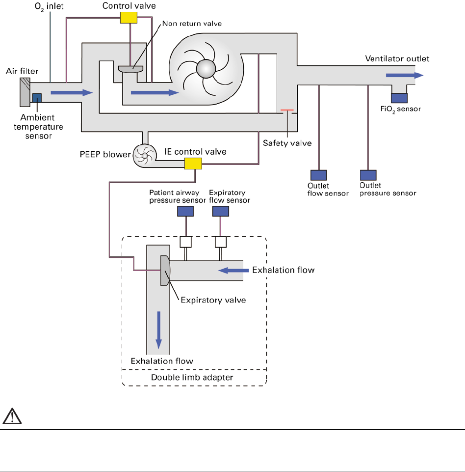
Technical specifications
76
Pneumatic flow path
WARNING
Under normal or single fault conditions the entire pneumatic flow path can become contaminated
with body fluids or expired gases if antibacterial filters are not installed on the ventilator outlet and
double limb adapter exhalation port.

Technical specifications
English 77
Guidance and Manufacturer’s Declaration Electromagnetic Emissions
& Immunity
Medical electrical equipment needs special precautions regarding EMC and needs to be installed and put
into service according to EMC information provided in this document.
This declaration currently applies for the following ResMed devices:
• Astral™ Series of Ventilators.
Guidance and manufacturer’s declaration—electromagnetic emissions
These devices are intended for use in the electromagnetic environment specified below. The customer
or the user of the device should assure that the device is used in such an environment.
Emissions test
Compliance
Electromagnetic environment—guidance
RF emissions CISPR 11
Group 1
The device uses RF energy only for its internal
function. Therefore, its RF emissions are very low
and are not likely to cause any interference in
nearby electronic equipment.
RF emissions CISPR 11
with or without USB adapter
with or without Oximeter adapter
Class B
The device is suitable for use in all establishments,
including domestic establishments and those
directly connected to the public low-voltage
network that supplies buildings used for domestic
purposes.
Harmonic Emissions
IEC 61000-3-2
with or without specified accessories
Class A
Voltage Fluctuations/Flicker Emissions
IEC 61000-3-3
with or without specified accessories
Complies
WARNING
• The device should not be used adjacent to or stacked with other equipment. If adjacent or
stacked use is necessary, the device should be observed to verify normal operation in the
configuration in which it will be used.
• The use of accessories other than those specified for the device is not recommended. They
may result in increased emissions or decreased immunity of the device.
• Additional equipment connected to medical electrical equipment must comply with the
respective IEC or ISO standards (eg, IEC 60950 for data processing equipment). Furthermore all
configurations shall comply with the requirements for medical electrical systems (see
IEC 60601-1-1 or clause 16 of the 3Ed. of IEC 60601-1, respectively). Anybody connecting
additional equipment to medical electrical equipment configures a medical system and is
therefore responsible that the system complies with the requirements for medical electrical
systems. Attention is drawn to the fact that local laws take priority over the above mentioned
requirements. If in doubt, consult your local representative or the technical service department.
• Portable RF communications equipment (including peripherals such as antenna cables and
external antennas) should be used no closer than 30 cm to any part of the device, including
cables specified by the manufacturer. Otherwise, degradation of the performance of this
equipment could result.

Technical specifications
78
Guidance and manufacturer’s declaration – electromagnetic immunity
These devices are intended for use in the electromagnetic environment specified below. The customer
or the user of the device should assure that the device is used in such an environment.
Immunity test
IEC60601-1-2 test
level, Ed. 4
Compliance level
Electromagnetic environment—guidance
Electrostatic
discharge (ESD)
IEC 61000-4-2
±8 kV contact
±15 kV air
±8 kV contact
±15 kV air
Floors should be wood, concrete or ceramic tile. If
floors are covered with synthetic material, the
relative humidity should be at least 30%.
Electrical fast
transient/burst
IEC 61000-4-4
±2 kV for power
supply lines
±1 kV for
input/output lines
±2 kV for power
supply lines
±1 kV for input/output
lines
Mains power quality should be that of a typical
commercial or hospital environment.
Surge
IEC 61000-4-5
±1 kV differential
mode
±2 kV common mode
±1 kV differential
mode
±2 kV common mode
Mains power quality should be that of a typical
commercial or hospital environment.
Voltage dips,
short
interruptions
and voltage
variations on
power supply
input lines
IEC 61000-4-11
<5% Ut (>95% dip in
Ut) for 0.5 cycle
40% Ut (60% dip in
Ut) for 5 cycles
70% Ut (30% dip in
Ut) for 25 cycles
<5% Ut (>95% dip in
Ut) for 5 sec
<12V (>95% dip in
240V) for 0.5 cycle
96V (60% dip in 240V)
for 5 cycles
168V (30% dip in
240V) for 25 cycles
<12V (>95% dip in
240V) for 5 sec
Mains power quality should be that of a typical
commercial or hospital environment.
If the user of the device requires continued
operation during power mains interruptions, it is
recommended that the device be powered from an
uninterruptible power source.
The internal battery will provide backup power of
eight hours.
Power
frequency
(50/60 Hz)
magnetic field
IEC 61000-4-8
30 A/m
30 A/m
Power frequency magnetic fields should be at levels
characteristic of a typical location in a typical
commercial or hospital environment.
Conducted RF
for life support
IEC 61000-4-6
3 Vrms
outside ISM bands
10 Vrms
inside ISM bands
10 Vrms
150 kHz to 80 MHz
Portable and mobile RF communications equipment
should be used no closer to any part of the device,
including cables, than the recommended separation
distance calculated from the equation applicable to
the frequency of the transmitter. See separation
distance table below.
d = 0.35 √P outside ISM bands
d = 1.2 √P inside ISM bands

Technical specifications
English 79
Immunity test
IEC60601-1-2 test
level, Ed. 4
Compliance level
Electromagnetic environment—guidance
Radiated RF
IEC 61000-4-3
10 V/m
80 MHz to 2.5 GHz
for Home
environment
10 V/m
80 MHz to 2.5 GHz
Recommended separation distance for life
support equipment
d = 1.2 √P 80 MHz to 800 MHz
d = 2.3 √P 800 MHz to 2.5 GHz
Where (P) is the maximum output power rating of
the transmitter in watts (W) according to the
transmitter manufacturer and d is the recommended
separation distance in meters (m). Field strengths
from fixed RF transmitters, as determined by an
electromagnetic site survey,
a
should be less than the
compliance level in each frequency range.
b
Interference may occur in the vicinity of equipment
marked with the following symbol:
a
Field strengths from fixed transmitters, such as base stations for radio (cellular/cordless) telephones and land
mobile radios, amateur radio, AM and FM radio broadcast and TV broadcast cannot be predicted theoretically with
accuracy. To assess the electromagnetic environment due to fixed RF transmitters, an electromagnetic site survey
should be considered. If the measured field strength in the location in which the device is used exceeds the
applicable RF compliance level above, the device should be observed to verify normal operation. If abnormal
performance is observed, additional measures may be necessary, such as reorienting or relocating the device.
b
Over the frequency range 150 kHz to 80 MHz, field strengths should be less than 10 V/m.
Notes:
• Ut is the AC mains voltage prior to application of the test level.
• At 80 MHz and 800 MHz, the higher frequency range applies.
• These guidelines may not apply in all situations. Electromagnetic propagation is affected by absorption and
reflection from structures, objects and people.
• ISM bands: 6.765 to 6.795MHz, 13.533 to 13.567MHz, 26.957 to 27.283MHz and 40.66 to 40.70Mz

Technical specifications
80
Recommended separation distances between portable and mobile RF
communications equipment and the life support device
These devices are intended for use in an environment in which radiated RF disturbances are controlled.
The customer or the user of the device can help prevent electromagnetic interference by maintaining a
minimum distance between portable and mobile RF communications equipment (transmitters) and the
device as recommended below, according to the maximum output power of the communications
equipment.
Rated maximum
output power of
transmitter (W)
Separation distance according to frequency of transmitter (m)
150 kHz to 80 MHz
Outside ISM bands
d = 0.35 √P
150 kHz to 80 MHz
Inside ISM bands
d = 1.2 √P
80 MHz to 800
MHz
d = 1.2 √P
800MHz to 2.5 GHz
d = 2.3 √P
0.01
0.1
0.1
0.1
0.2
0.1
0.1
0.4
0.4
0.7
1
0.4
1.2
1.2
2.3
10
1.1
3.8
3.8
7.3
100
3.5
12.0
12.0
23.0
For transmitters rated at a maximum output power not listed above, the recommended separation
distance d in metres (m) can be determined using the equation applicable to the frequency of the
transmitter, where P is the maximum output power rating of the transmitter in watts (W) according to
the transmitter manufacturer.
Notes:
• At 80 MHz and 800 MHz, the separation distance for the higher frequency range applies.
• These guidelines may not apply in all situations. Electromagnetic propagation is affected by absorption and
reflection from structures, objects and people.
Potential impact of electromagnetic disturbances
The loss or degradation of the following clinical functions due to electromagnetic disturbances could
result in compromised patient safety:
• Accuracy of ventilation control
• Accuracy of monitoring of airway pressure, expired volume and FiO
2
• Therapy alarms.
Detection of this degradation could be observed by the following device behaviour:
• Erratic ventilation delivery
• Rapid fluctuations in monitored parameters
• False activation of therapy or technical alarms (eg, System Fault or Battery comms lost alarms)
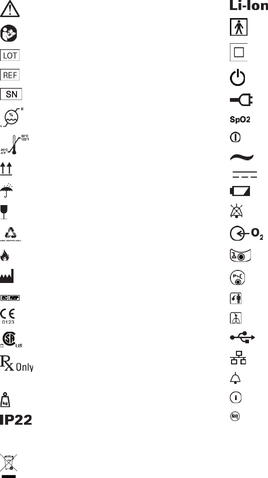
Symbols
English 81
Symbols
The following symbols may appear on your product or packaging.
Indicates a Warning or Caution
Follow instructions for use
Batch code
Catalogue number
Serial number
Humidity Limitation
Temperature Limitation
Keep upright
Keep dry
Fragile, handle with care
Recyclable
Fire if damaged
Manufacturer
European Authorised Representative
CE Labelling in accordance with EC directive 93/42/EEC
Canadian Standards Association
Prescription only (In the US, Federal law restricts
these devices to sale by or on the order of a physician.)
Device weight
Protected against finger sized objects. Protected
against dripping water when tilted up to 15 degrees from
specified orientation.
Lithium Ion battery
Type BF applied part
Class II equipment
On/Off
Power plug
Oximeter connector
Ventilation indicator
Alternating current
Direct current
Battery
Alarm Mute / Reset (Audio Pause)
Oxygen supply inlet connector
Connector for control line of external expiratory valve
Connector for the breathing pressure measuring line
Expiratory Connector (From Patient)
Inspiratory Connector (To Patient)
USB connector
Ethernet connector
Remote Alarm connector
Remote Alarm Test button
MR unsafe (do not use in the vicinity of an MRI device).
Environmental information
This device should be disposed of separately, not as unsorted municipal waste. To dispose of your
device, you should use appropriate collection, reuse and recycling systems available in your region. The
use of these collection, reuse and recycling systems is designed to reduce pressure on natural resources
and prevent hazardous substances from damaging the environment.
If you need information on these disposal systems, please contact your local waste administration. The
crossed-bin symbol invites you to use these disposal systems. If you require information on collection
and disposal of your ResMed device please contact your ResMed office, local distributor or go to
ResMed.com/environment.
Standards compliance
82
Standards compliance
The Astral meets the following standards:
• IEC 60601-1 Medical Electrical Equipment - General Requirements for Basic Safety and Essential
Performance
• IEC 60601-1-2 Medical electrical equipment - Part 1-2: General requirements for basic safety and
essential performance - Collateral standard: Electromagnetic compatibility -Requirements and tests
• IEC 60601-1-8 General requirements, test and guidance for alarm systems in medical electrical
equipment and medical electrical systems
• IEC 60601-1-11 Medical electrical equipment - Part 1-11: General requirements for basic safety and
essential performance - Collateral standard: Requirements for medical electrical equipment and
medical electrical systems used in the home healthcare environment
• ISO 80601-2-72 Medical electrical equipment - Part 2-72: Particular requirements for basic safety and
essential performance of home healthcare environment ventilators for ventilator-dependent patients
Training and support
For training and support materials, please contact your ResMed representative.

Limited warranty
English 83
Limited warranty
ResMed Pty Ltd (hereafter 'ResMed') warrants that your ResMed product shall be free from
defects in material and workmanship from the date of purchase for the period specified below.
Product Warranty period
• Mask systems (including mask frame, cushion, headgear and tubing)—excluding
single-use devices
• Accessories—excluding single-use devices
• Flex-type finger pulse sensors
• Humidifier water tubs
90 days
• Batteries for use in ResMed internal and external battery systems
6 months
• Clip-type finger pulse sensors
• CPAP and bilevel device data modules
• Oximeters and CPAP and bilevel device oximeter adapters
• Humidifiers and humidifier cleanable water tubs
• Titration control devices
1 year
• CPAP, bilevel and ventilation devices (including external power supply units)
• Battery accessories
• Portable diagnostic/screening devices
2 years
This warranty is only available to the initial consumer. It is not transferable.
If the product fails under conditions of normal use, ResMed will repair or replace, at its option,
the defective product or any of its components.
This Limited Warranty does not cover: a) any damage caused as a result of improper use,
abuse, modification or alteration of the product; b) repairs carried out by any service
organization that has not been expressly authorized by ResMed to perform such repairs; c) any
damage or contamination due to cigarette, pipe, cigar or other smoke; and d) any damage
caused by water being spilled on or into an electronic device.
Warranty is void on product sold, or resold, outside the region of original purchase.
Warranty claims on defective product must be made by the initial consumer at the point of
purchase.
This warranty replaces all other expressed or implied warranties, including any implied warranty
of merchantability or fitness for a particular purpose. Some regions or states do not allow
limitations on how long an implied warranty lasts, so the above limitation may not apply to you.
ResMed shall not be responsible for any incidental or consequential damages claimed to have
resulted from the sale, installation or use of any ResMed product. Some regions or states do
not allow the exclusion or limitation of incidental or consequential damages, so the above
limitation may not apply to you.
This warranty gives you specific legal rights, and you may also have other rights which vary
from region to region. For further information on your warranty rights, contact your local
ResMed dealer or ResMed office.

Appendix A: Definitions
84
Appendix A: Definitions
Ventilation settings definitions
The available settings will vary with the selection of the ventilation mode. Each mode details the settings
available.
Setting Definition
Apnea Definition
Apnea Definition sets the type of breath which must be delayed for an apnea to be
detected.
Apnea Interval
(T apnea)
Apnea Interval (T apnea) sets the period without breath or spontaneous breath required
for an apnea to be detected.
Apnea Response Apnea Response sets the behaviour of the ventilator when an apnea is detected.
Circuit Type
Circuit Type sets whether a Double limb circuit, Single limb circuit with expiratory valve
or Single limb circuit with intentional leak is in use.
CPAP
Continuous Positive Airway Pressure (CPAP) sets the pressure maintained throughout a
spontaneous breath.
Cycle
Cycle (also known as Expiratory Trigger) sets the threshold where start of expiration
within a breath is detected.
EPAP
Expiratory Positive Airway Pressure (EPAP) sets the pressure to be delivered to the
patient during expiration.
Flow shape Sets the target flow waveform for the delivery of mandatory controlled volume breaths.
Inspiratory duration option
(Insp Duration Option)
Inspiratory duration option (Insp Duration Option) sets whether Inspiration Time (Ti) or
Peak Inspiratory Flow (PIF) is used to configure volume controlled breaths.
Interface type Invasive, mask, or mouthpiece
Interval Sigh interval sets the period between sigh breaths.
IPAP
Inspiratory Positive Airway Pressure (IPAP) sets the pressure to be delivered to the
patient during inspiration.
Magnitude
Magnitude sets the size of the manual or sigh breath delivered relative to the size of the
normal ventilation breath. Separate magnitude settings are available for configuration of
manual or sigh breaths.
Manual Breath Manual Breath sets whether a manual breath is available for delivery.
Mask Type
Mask Type sets the type of mask or in-line vent in use when the circuit type is single
with leak.
Max EPAP
Maximum Expiratory Positive Airway Pressure (Max EPAP) sets the maximum pressure to
be delivered to the patient during expiration to maintain upper airway patency.
Max PS
Maximum Pressure Support (Max PS) sets the maximum pressure support above EPAP
allowed to achieve the Target Va.
Min EPAP
Minimum Expiratory Positive Pressure (Min EPAP) sets the minimum pressure allowed to
be delivered to the patient during expiration to maintain upper airway patency.
The Min EPAP should be set to treat any lower airway condition.
Min PS
Minimum Pressure Support (Min PS) sets the minimum pressure support above EPAP
allowed to achieve the Target Va (iVAPS).
P control
Pressure control (P control) sets the pressure support above PEEP to be delivered during
inspiration for pressure assisted breaths.

Appendix A: Definitions
English 85
Setting Definition
P control max
Maximum allowed pressure control (P control max) sets the maximum pressure control
above PEEP allowed to achieve the target safety volume.
Patient type
Select from Adult or Pediatric. This setting configures the default values and ranges
available for ventilation settings and determines circuit resistance acceptance criteria
applied in the Learn Circuit.
PEEP Positive End Expiratory Pressure (PEEP) sets the pressure maintained during exhalation.
PIF
Peak Inspiratory Flow (PIF) sets the maximum delivered flow for volume controlled
breaths.
PS
Sets the pressure support above PEEP to be delivered during inspiration for pressure
supported breaths (spontaneous breaths).
PS Max
Maximum allowed Pressure Support (PS Max) sets the maximum pressure support above
PEEP allowed to achieve the target safety tidal volume.
Pt Height
Patient Height (Pt Height) is used to estimate the patient's anatomical deadspace and
Ideal Body Weight (IBW).
Resp. rate
Respiratory rate (Resp. rate) sets the breaths per minute (bpm) to be delivered by the
ventilator to the patient. The measured respiratory rate may be greater due to patient
triggered breaths.
Rise Time
Rise time sets the time taken for the ventilator to reach inspiratory pressure for pressure
controlled breaths.
Safety Vt
Safety tidal volume sets the target minimum tidal volume (Vt) for each ventilator
delivered breath.
Sigh Alert
Sigh alert sets whether the ventilator gives a single beep just prior to delivery of a sigh
breath.
Sigh Breath
Sigh Breath sets whether a magnified breath (a sigh breath) will be delivered at the sigh
interval.
Target Pt Rate
Target Patient Rate (Target Pt Rate) sets the upper boundary for the iVAPS intelligent
Backup Rate (iBR).
Target Va
Target Alveolar Minute Ventilation (Target Va) sets the servo-ventilation target for
iVAPS.
Ti Inspiration time (Ti) sets the duration of the inspiratory phase of a breath.
Ti Max
Maximum inspiratory time (Ti Max) sets the maximum duration of the inspiratory phase
of a breath.
Ti Min
Minimum Inspiratory Time (Ti Min) set the minimum duration of the inspiratory phase of
a breath.
Trigger Sets the trigger threshold above which the ventilator triggers a new breath.
The trigger is blocked for the first 300 ms following the start of exhalation.
Trigger type
Trigger type sets whether a pressure based trigger threshold or flow based trigger
threshold is used when a Double circuit is selected.
Vt
The Tidal Volume (Vt) sets the volume of gas, measured in mL, to be delivered to the
patient in a mandatory controlled volume breath.

Appendix A: Definitions
86
Measured and calculated parameter definitions
The following measured and calculated parameters are displayed during configuration or during
ventilation. Each Ventilation mode details the parameters displayed.
Parameter Definition
FiO
2
Average of percentage of Oxygen delivered to circuit.
I:E I:E is the ratio of the inspiratory period to the expiratory period.
The measured I:E ratio is displayed as a monitored parameter during ventilation.
The expected I:E ratio is calculated and displayed on the settings screens if the Resp.
rate setting is not set to Off.
Leak
Leak is the average unintentional leak. It is reported as a percentage for Double limb
circuits and as a flow for Single limb circuits with intentional leak.
The measured Leak is displayed as a monitored parameter during ventilation.
MV
Minute Ventilation (MV) is the product of the Target Patient Rate (Target Pt Rate) and
expired tidal volume averaged over the last eight breaths.
The MV is displayed as a calculated parameter during iVAPS configuration.
MVe
Expiratory Minute Volume (MVe) is the product of the respiratory rate and expired tidal
volume averaged over the last eight breaths.
The measured MVe is displayed as a monitored parameter during ventilation.
MVi
Inspiratory Minute Volume (MVi) is the product of the respiratory rate and inspired tidal
volume averaged over the last eight breaths.
The measured MVi is displayed as a monitored parameter during ventilation.
Pressure Pressure is the current airway pressure of the patient as measured at the patient port.
The measured Pressure is displayed as a monitored parameter during ventilation.
PEEP
End expiratory pressure (PEEP) is the airway pressure measured 50 ms prior to the end of
the last expiration.
The measured PEEP is displayed as a monitored parameter during ventilation.
Pmean Mean airway pressure of the patient over the last breath.
% Spont cycle
% Spont cycle is the percentage of breaths that are spontaneously cycled over the past
20 breaths.
% Spont trig
% Spont trig is the percentage of breaths that are spontaneously triggered over the last
20 breaths.
The measured %Spont Trig is displayed as a monitored parameter during ventilation.
PIF Peak Inspiratory Flow (PIF) is the maximum flow reached during the last inspiration.
The measured PIF is displayed as a monitored parameter during ventilation.
The expected PIF is calculated and displayed for volume controlled breaths on the
settings screens when the Inspiratory Phase Duration Option is set to Ti.
PIP
Peak Inspiratory Pressure (PIP) is the maximum airway pressure reached during the last
inspiration.
The measured PIP is displayed as a monitored parameter during ventilation.
Pulse rate
The measured Pulse rate (pulse) is displayed as a monitored parameter when a pulse
oximeter is used.

Appendix A: Definitions
English 87
Parameter Definition
Resp. rate
Respiratory rate (Resp. rate) is the number of breaths per minute averaged over the last
eight breaths.
The measured Resp. rate is displayed as a monitored parameter during ventilation.
RSBI
Rapid Shallow Breathing Index (RSBI) is calculated by dividing the breath rate by Tidal
Volume.
The measured RSBI is displayed as a monitored parameter during ventilation.
SpO
2
The measured functional Oxygen Saturation (SpO
2
) is displayed as a monitored
parameter when a pulse oximeter is used.
Te Expiratory time Te is the period in seconds of the last expiratory phase.
Ti Inspiratory time Ti is the period in seconds of the last inspiratory phase.
The measured Ti is displayed as a monitored parameter during ventilation.
The expected Ti is calculated and displayed for volume controlled breaths on the settings
screens when the Inspiratory Phase Duration Option is set to PIF.
Va
Alveolar Minute Ventilation (Va) is calculated by (Tidal Volume - Deadspace) x Resp.
Rate.
The measured Va is shown as a monitored parameter during ventilation.
Vte Expiratory Tidal Volume (Vte) is the volume expired during the last breath.
The measured Vte is displayed as a monitored parameter during ventilation.
Vti Inspiratory Tidal Volume (VTi) is the volume inspired during the last breath.
The measured VTi is displayed as a monitored parameter during ventilation.
Average Vt
Average Tidal Volume (Average Vt) is the average volume expired during the last five
minutes of ventilation.
The Average Vt is displayed as a calculation parameter during iVAPS configuration.
Average Vt/kg
Average Tidal Volume per kg (Average Vt/kg) is the Average Vt divided by Ideal Body
Weight (IBW).
The Average Vt is displayed as a calculation parameter during iVAPS configuration.

ResMed.com
ResMed Pty Ltd
1 Elizabeth Macarthur Drive, Bella Vista NSW 2153 Australia
See ResMed.com for other ResMed locations worldwide. Astral, AirView and ResScan are trademarks and/or registered trademarks of the ResMed family of companies. For patent and other intellectual
property information, see ResMed.com/ip. Aerogen and Aeroneb are registered trademarks of Aerogen, Inc. NONIN is a trademark of Nonin Medical, Inc. Velcro is a trademark of Velcro Industries B.V.
© 2018 ResMed. 278552/1 2018-05
